3-5
Connecting TM I/O to PCS 7
C79000-G8076-C710-04
Insert and screw-tighten the 24 VDC/24 VDC power supply module in the
outer left slot (slot 1). Select your mains voltage with the selector switch on
the power supply module.
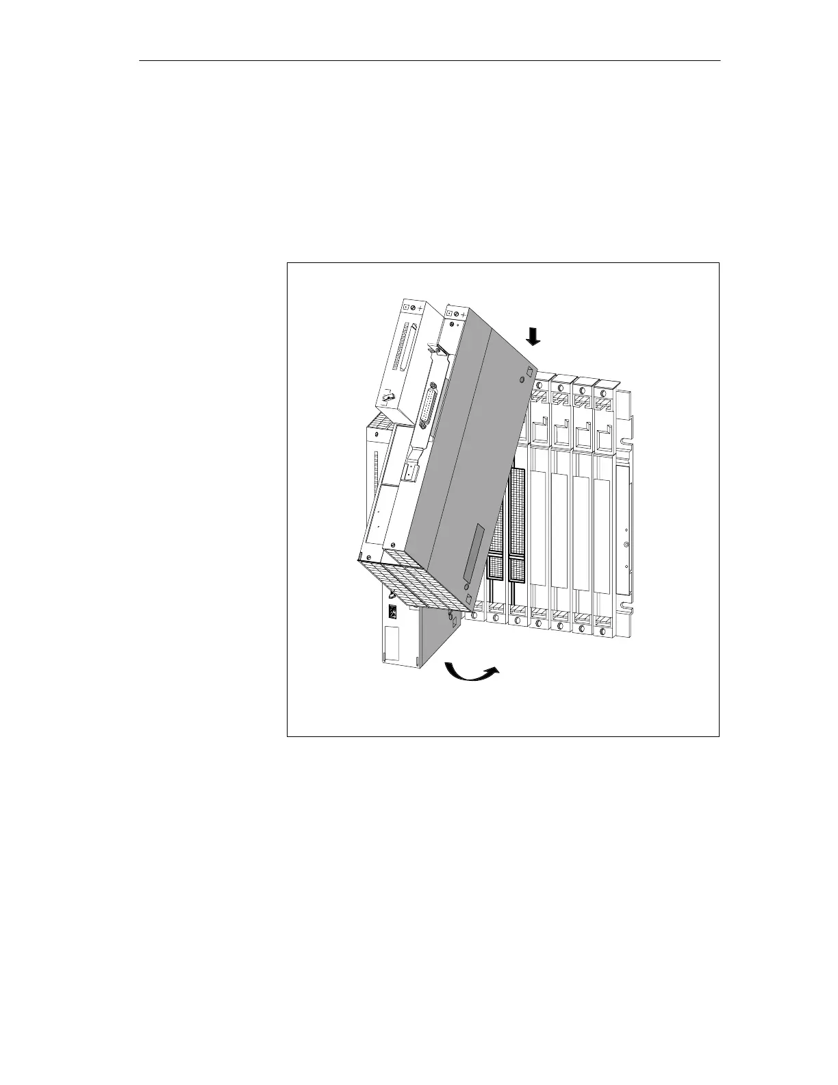
Insert the module group to the right side of the CPU (1) and swing it down
(2). See Figure 3-3.
1
2
Figure 3-3 Inserting the modules
Screw-tighten central/expansion module unit.
Do not yet insert the Memory Card into the central module.
Set the key switch on the central module to STOP position.
Insert the backup batteries (2 pieces) in the power supply (time-of-day).
PS 405
Inserting modules
Screw-tightening
the module unit
Memory Card
Inserting the key
switch
Backup battery
Commissionin
 Loading...


