5-15
Connecting TM I/O to PCS 7
C79000-G8076-C710-04
At every startup of PCS7/TM, the TPM 478-2 software performs an initiali-
zation and self-test routine.
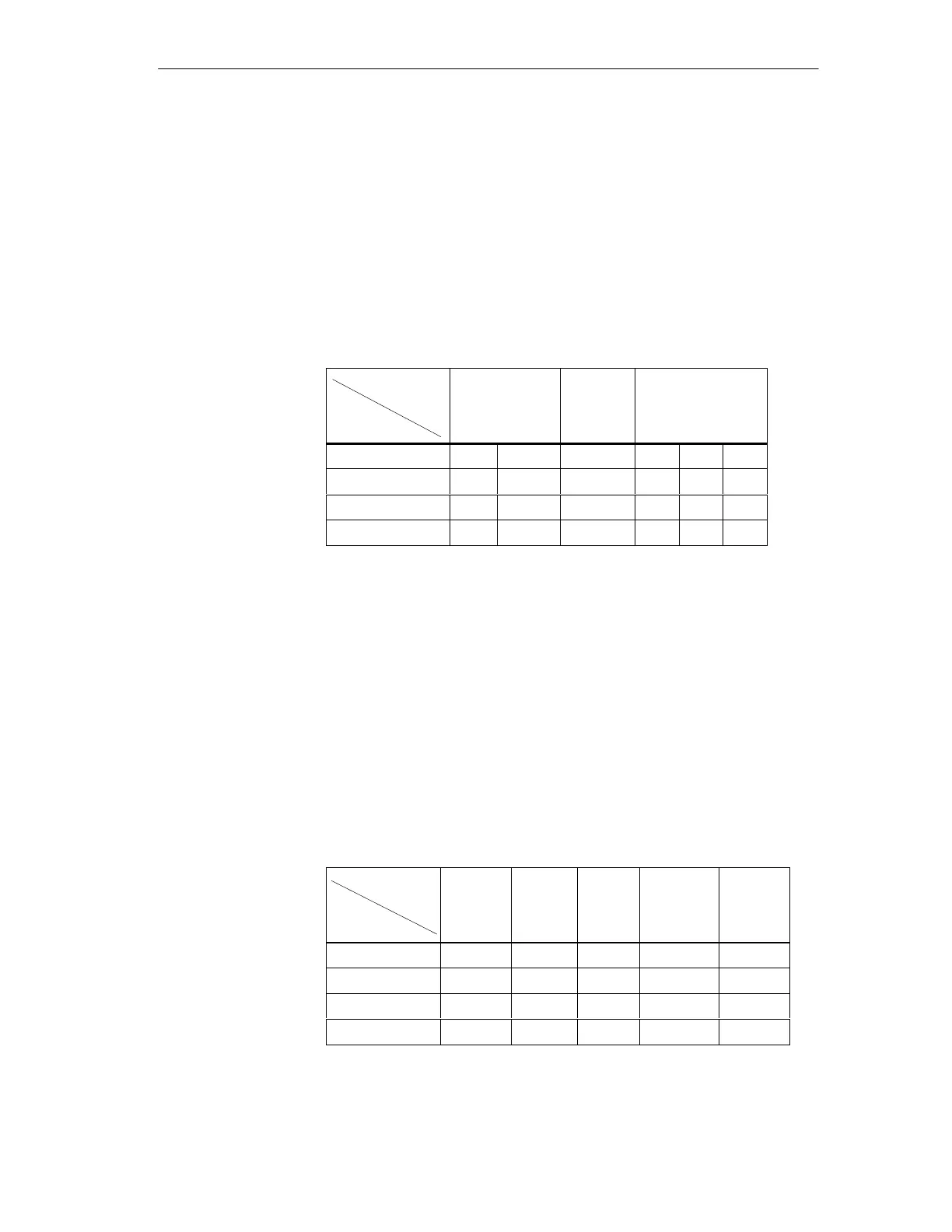
LEDs 6-10 on the TPM 478-2 front panel provide information on operation
and startup behavior of I/O communication, thus enabling quick diagnostics
if an error occurs. The I/O startup behavior of TPM 478-2 is shown in Table
4-1 (sequence from left to right).
The table shows only some of the important phases. Depending on the PLC
software version and user structure, there are additional dark phases. In every
situation only the RUN LED is lit after startup of the I/O bus system (cyclic
operation).
Table 5-1
Meaning
Display
Coordination Initializa-
tion/Self-
test
I/O bus system star-
tup
EIO (red) 0 0 0 0 0 0
PQA (yellow) 0 x x 0 x 0
PQB (yellow) 0 0 x x x 0
RUN (green) 0 0 0 0 x x
0 ¢ LED is OFF
x ¢ LED is ON
The fast coordination phase is hardly perceptible.
After a successful init/self-test phase, TPM 478-2 performs the startup of the
I/O bus system.
If an error is detected, TPM 478-2 interrupts startup and goes into STOP (red
LED EIO is lit). TPM 478-2 is defective if it stays in STOP state even after
several reset operations. When you return a defective module to the Electro-
nics Plant in Karlsruhe (EWK), Germany, specify which error displays have
occurred. See Table 5-2.
Table 5-2 Error displays on startup
Meaning
Display
Error in
local
RAM
DPRAM
error
Address
bus er-
ror
Program
memory
error
Watch-
dog error
EIO (red) x x x x x
PQA (yellow) x 0 x 0 x
PQB (yellow) 0 x x 0 x
RUN (green) 0 0 0 0 x
0 ¢ LED is ON
x ¢ LED is OFF
TPM 478-2:
Diagnostics of
I/O communication
Coordination
Initialization/
Selftest
Interface module TPM 478-2
 Loading...


