EasyManuals Logo

Siemens Simatic S7-400 Function Manual

Siemens Simatic S7-400
332 pages
To Next Page IconTo Next Page
To Previous Page IconTo Previous Page
Page #306 background imageLoading...
Page #306 background image
7 Establishing a connection and diagnostics 03/2012
7.1 Connecting the machine
© Siemens AG 2006-2013 All Rights Reserved
7-306 SINUMERIK Integrate AMB, AMC, AMM, Function Manual (FH) - 03/2012
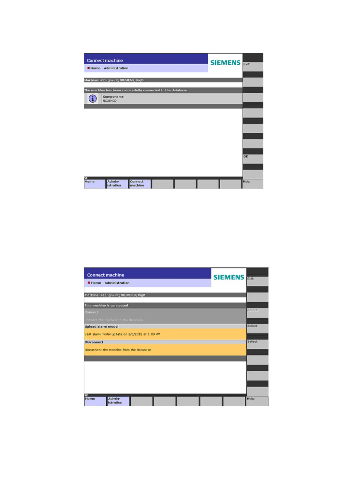
Fig. 7-6: Connection to the machine - success message.
7.1.1 Uploading an alarm model
Operating sequence on the machine
Language-specific alarm texts are made available on the server. This allows alarm
messages to be displayed in the currently set browser language.
Fig. 7-7: Upload the alarm model

Table of Contents

Other manuals for Siemens Simatic S7-400

Questions and Answers:

Question and Answer IconNeed help?

Do you have a question about the Siemens Simatic S7-400 and is the answer not in the manual?

Siemens Simatic S7-400 Specifications

General IconGeneral
Programming LanguageSTEP 7 (LAD, FBD, STL, SCL, GRAPH)
Communication InterfacesMPI, PROFIBUS
Power Supply24 V DC, 120/230 V AC (Power supply modules are separate and chosen based on system requirements)
Operating Temperature0°C to 60°C
MountingRack mounting
ProcessorCPU 412-1, CPU 414-2, CPU 416-2, CPU 417-4 (Different CPUs offer varying performance and features)
Relative Humidity5 to 95% (non-condensing)

Related product manuals