4
4.3 Parameter area (PKW area)
4-129
E Siemens AG 2013 All Rights Reserved
SIMODRIVE POSMO A User Manual (POS1) – 08/2013 Edition
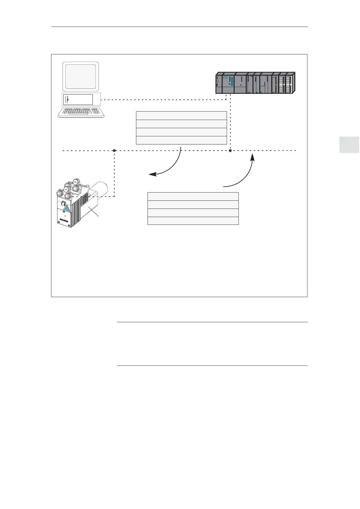
PROFIBUS–DP
SIMATIC S7–300 (CPU: S7–315–2–DP)
MPI
Output signals at
the DP slave
Input signals at
the DP slave
PKW area (task)
PAW 256 = 1000 0000 0101 0001
PAW 258 = 0000 0100 0000 0000
PAW 260 = 00 78
hex
(e.g.)
PAW 262 = 02 A8
hex
(e.g.)
IND
PKE
PWE1
PWE2
AK = 8, PNU = 81
Index = 4
Value (high)
Value (low)
PKW area (response)
PEW 256 = 0101 0000 0101 0001
PEW 258 = 0000 0100 0000 0000
PEW 260 = 00 78
hex
(e.g.)
PEW 262 = 02 A8
hex
(e.g.)
IND
PKE
PWE1
PWE2
AK = 5, PNU = 81
Index = 4
Value (high)
Value (low)
PAW Peripheral output word
PEW Peripheral input word
PKE Parameter ID
IND Sub–index, sub–parameter number, array index
PWE Parameter value
AK Task and response ID
PNU Parameter number
PG/PC
DP slave
POSMO A
Fig. 4-8 Example: Writing parameters via PROFIBUS
Note
The SIMATIC S7 ”FB 11” block can be used to ”write parameters via
PROFIBUS”.
––> Refer to Chapter 3.2.2
4 Communications via PROFIBUS–DP
02.9902.00