3.3 Commissioning an axis
3-92
E Siemens AG 2013 All Rights Reserved
SIMODRIVE POSMO A User Manual (POS1) – 08/2013 Edition
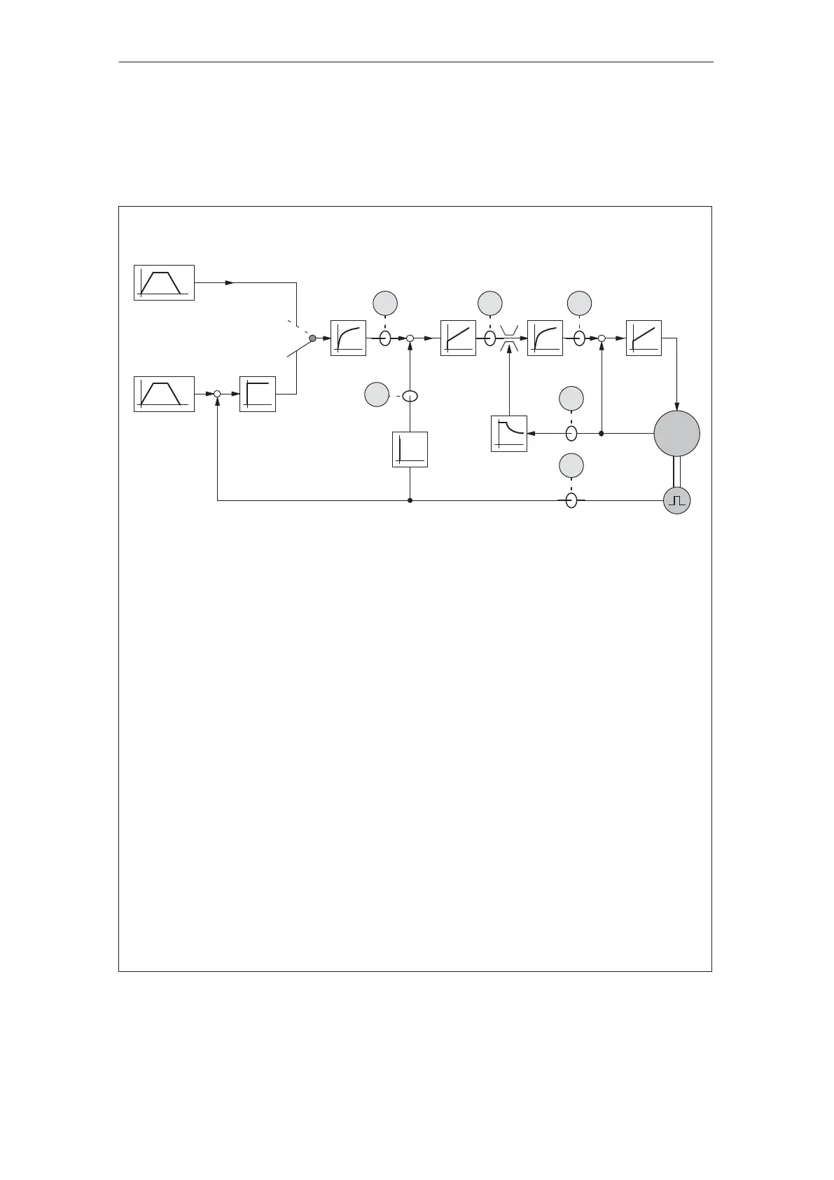
3.3.1 Control structure positioning (pos mode)
The structure of the current/speed and position controller in the
”positioning” mode (pos mode) is shown in the following figure.
Parameter
P8 Maximum speed
P9 Ramp–up time
P10 Maximum velocity
P13 Monitoring time (zero speed monitoring,
activation of holding and standstill controller)
P15 Backlash compensation
P16 Maximum overcurrent
P17 P gain, n controller
P18 Integral action time, n controller
P19 Kv factor (position loop gain)
P20 Current setpoint smoothing
P21 Speed setpoint smoothing
P22 Maximum acceleration
P23 Jerk time constant
P28 Maximum current
P54
1)
P gain, n controller, standstill (if P56.2 = 1, this was standard before SW 1.3)
P57
1)
P gain, holding controller, standstill (if P56.2 = 0, this was standard from SW 1.3)
Note:
Additional information on the parameters is provided in the parameter list.
––> Refer to Chapter 5.6.2
1)From SW 1.3 the factory presetting is “Holding controller active” (P56.2 = 0). The holding controller
is switched-in when the standstill monitoring function has been activated. We recommend that this
factory presetting remains unchanged. The holding controller has a standstill-optimized control
structure.
P8
P9
P23
M
i
act
s
act
i
set
n
set
n
set
s
set
P10
P15
P22
P23
P19
P57
P21 P17
P54
P18 P20
P16 P28
Closed–loop
speed controlled
Closed–loop
position
controlled
Program control word
(PSW.0)
0
1
u
653
2
1
4
Measuring signals
1 Current actual value
2 Speed actual value
3 Speed setpoint
4 Position actual value
5 Current setpoint from the speed controller
6 Current setpoint smoothed
Note:
These signals can be output via the analog
measuring outputs.
––> Refer to Chapter 6.3
––
–
Current
regulator
Speed
controller
Position controller
Fig. 3-9 Closed–loop structure for the ”positioning” mode for SIMODRIVE POSMO A
Description
02.9905.0310.07