6
6.3 Analog test outputs
6-250
E Siemens AG 2013 All Rights Reserved
SIMODRIVE POSMO A User Manual (POS1) – 08/2013 Edition
6.3 Analog test outputs
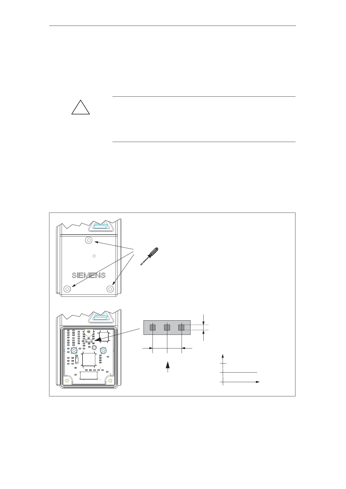
Analog test outputs are provided at the rear of the SIMODRIVE POSMO A
which are only accessible after the cover has been unscrewed.
!
Caution
Measurements may only be made in exceptional cases by
appropriately trained personnel. The ”correct” text sockets must be
used, as short–circuits will permanently damage the module (refer to
Fig. 6-1).
The following parameters are available for the analog test sockets:
S P33, P34, P35 address, shift factor and offset for DAU 1
S P36, P37, P38 address, shift factor and offset for DAU 2
Which signal is output via the test outputs?
S This is defined by entering an appropriate address in P33 or P36.
Test sockets:
0.64 mm
Pin 123
5 V
2.5 V
8 0 V of the
test signal
0 V
Test pins
0.64
Screw type: Counter–sunk screw
M4 x 12 – 8.8
SN 63261
SIMODRIVE POSMO A
with cover attached
SIMODRIVE POSMO A
with cover removed
2.54 2.54
X11
––> 75 W motor
Pin 321 ––> 300 W motor
Torx T15/80
max. 3.9 Nm
Pin Function
1 DAU 1
2 DAU 2
3 M (reference)
Fig. 6-1 SIMODRIVE POSMO A test sockets with the cover removed
Description
6 Fault Handling and Diagnostics
02.9904.0104.01