5
5.2 ”Speed setpoint” mode (P700 = 1) (from SW 2.0)
5-137
Siemens AG 2013 All Rights Reserved
SIMODRIVE POSMO A User Manual (POS1) – 08/2013 Edition
The software limit switches must remain de–activated so that the drive
can always rotate endlessly. This is the reason that in the speed set-
point mode the drive must be parameterized as rotary axis and be de–
referenced.
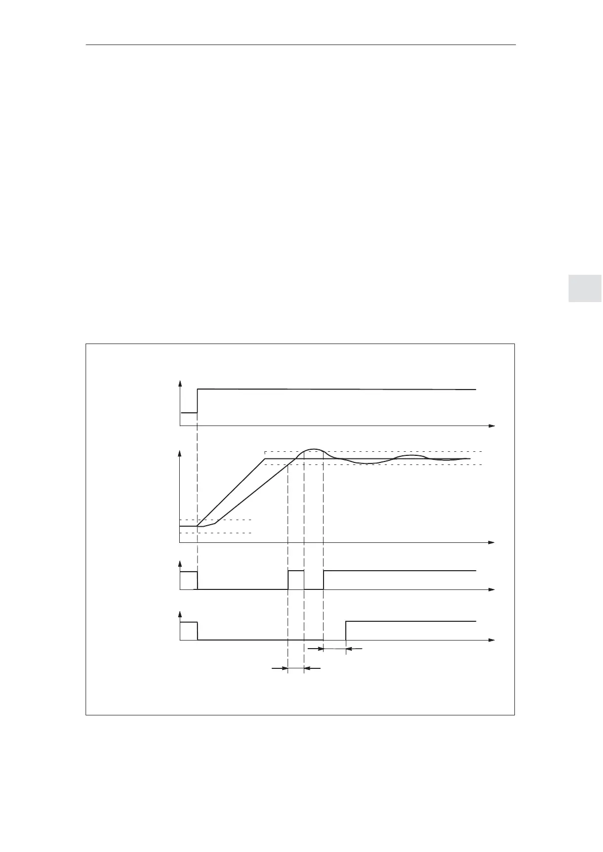
For the ramp–function generator, the following signals are used:
Input signals:
– Ramp–function generator enable (STW.4 = 1)
– Ramp–function generator start/ramp–function generator stop
(STW.5 = 1)
– Enable setpoint/inhibit setpoint (STW.6 = 1)
Output signals:
– Speed in the tolerance bandwidth/speed outside the tolerance
bandwidth (ZSW.8)
– Ramp–up completed/ramp–up not completed (ZSW.10)
Delay time P1427:
Ifnt > P1427, then ”ramp–up completed” (ZSW.10 = 1)
n
set
Ramp–up
completed
(ZSW.10)
n
set
n
act
P1426
RFG input
P1426
t
0
t
1
t
t
t
Speed in the
tolerance
bandwidth
(ZSW.8)
t
RFG output
nt = t
1
– t
0
nt > P1427
Fig. 5-2 Signal characteristics for the ramp–function generator
Input/output
signals for the
ramp–function
generator
5 Description of the Functions
02.9906.05