5
5.5 SIMODRIVE POSMO A functions
5-161
Siemens AG 2013 All Rights Reserved
SIMODRIVE POSMO A User Manual (POS1) – 08/2013 Edition
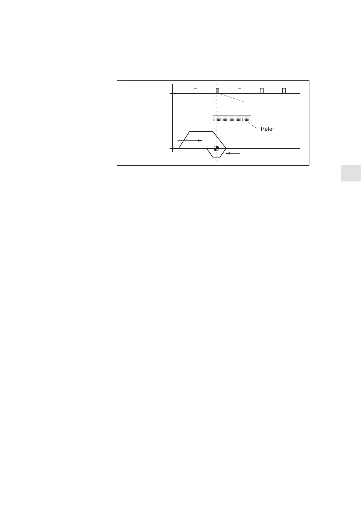
The reference point approach is executed via program. The axis tra-
verses with direction reversal depending on the reference cam signal.
Zero marks
Reference cam
signal
(e.g. from BERO)
Traversing
profile
Reference mark
Reference cams
Fig. 5-6 Reference approach to the BERO with direction reversal
Prerequisites:
Connect the reference cam signal to terminal 1
(X5, I/Q1, refer to Chapter 2.3)
Define terminal 1 as input and directly transfer the input terminal
signal into the start byte
(e.g. start byte bit 7 ––> P31 = 25, refer to Chapter 5.5.10)
Program the following traversing program (example):
Program block (e.g. block 13)
– SMStart bit 7 as start condition
– Program control word (PSW) = 224
dec
(00 1110 0000
bin
) (E0
hex
)
(closed–loop speed controlled, with approximate positioning, with
negated start byte, skip if the start byte is not fulfilled)
– Speed e.g. 20 % (= approach velocity)
– Acceleration 100 %
Program block (e.g. block 14)
– SMStart bit 7 as start condition
– Program control word (PSW)
= 384
dec
(01 1000 0000
bin
) (180
hex
)
(closed–loop speed controlled without negated start byte)
– Speed e.g. –5 %
(= shutdown velocity with direction reversal)
– Acceleration 100 %
– Program end when the end of the block is reached
Start program
As soon as ZSW.14 = ”0” (outside traversing block) is signaled, the
reference point can be set with STW.11 (start referencing/stop refer-
Reference
approach to a
BERO proximity
switch with
direction reversal
5 Description of the Functions
02.99