5
5.5 SIMODRIVE POSMO A functions
5-176
Siemens AG 2013 All Rights Reserved
SIMODRIVE POSMO A User Manual (POS1) – 08/2013 Edition
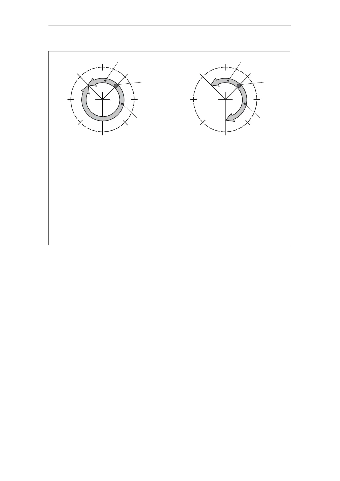
Positioning type = ABSOLUTE
Example 1 (PSW.12 = ”0”):
P81:4 = 315
P82:4 = –100
––> Traverse with 100 % to 315 negative
Example 2 (PSW.12 = ”0”):
P81:4 = 315
P82:4 = 100
––> Traverse with 100 % to 315 positive
Positioning type = RELATIVE
Example 1:
P81:4 = –90
P82:4 = 100
––> Traverse with 100 % through 90 negative
Example 2:
P81:4 = 135
P82:4 = 100
––> Traverse with 100 % through 135
45°
90°
135°
180°
225°
270°
315°
0°
45°
90°
135°
180°
225°
270°
315°
0° Example 1
Example 2
Start Start
Example 1
Example 2
Fig. 5-12 Example: Programming rotary axes
The following should be observed for the signaling position:
Before SW 1.3 the following applies:
– The drive has precisely one zero position (refer to Chapter
5.5.1). The signal position is viewed, referred to this position.
– A modulo evaluation is not made.
From SW 1.3, the following applies:
– The signal position is saved, evaluated as modulo value
The software limit switches act the same as for a linear axis.
P6 Software limit switch, start (refer to Chapter 5.6.2)
P7 Software limit switch, end
The software limit switches are de–activated with P6 = P7.
Signaling position
(P85:28)
Signaling position
(P55)
Software limit
switch
5 Description of the Functions
02.9904.01