2
2.2 Electrical system requirements
2-36
E Siemens AG 2013 All Rights Reserved
SIMODRIVE POSMO A User Manual (POS1) – 08/2013 Edition
The connection cover can be withdrawn and inserted under voltage
with the motor stationary (OFF 1).
If the PROFIBUS terminating resistor is not switched in on this node,
i.e. if this drive is not the first or last node, then communications to the
other bus nodes is not interrupted.
Notice
When the connection is withdrawn, the actual position is not saved.
This means that the drive must be re–referenced after the cover has
been inserted.
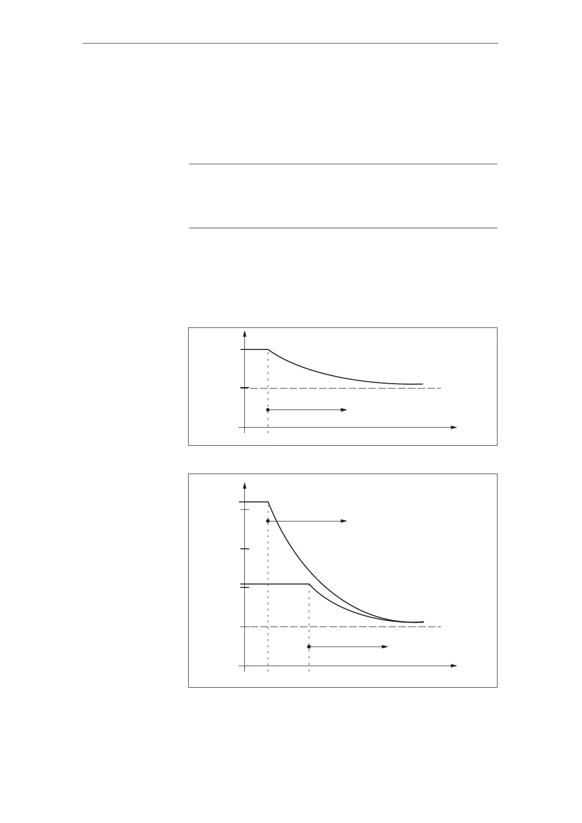
This limiting function protects the positioning motor against permanent
overload.
If the positioning motor is operated for an excessive time over the per-
missible load limit, then the available motor current is automatically lim-
ited according to a characteristic.
I [A]
t [s]
15
9
0
4.5
not to scale
Warning
801/P953.1 (refer to Chapter 6.2.2)
Fig. 2-7 i
2
t characteristic with 75 W motor
I [A]
t [s]
15
10.5
0
5
not to scale
10
21
15
20
60
Warning
801/P953.1 (refer to Chapter 6.2.2)
Warning
801/P953.1 (refer to Chapter 6.2.2)
Fig. 2-8 i
2
t characteristic with 300 W motor
Withdrawing/
inserting the
connection cover
under voltage
i
2
t limitation
2 Installing and Connecting–Up
02.99