2
2.2 Electrical system requirements
2-38
E Siemens AG 2013 All Rights Reserved
SIMODRIVE POSMO A User Manual (POS1) – 08/2013 Edition
If multiple axes are braked simultaneously in a system for operational
reasons, e.g. in the event of an EMERGENCY STOP or quasi–simulta-
neous traversing, a power management module (DC PMM) must be
used in order to convert the regenerative feedback energy.
The DC PMM is connected between the load power supply and the first
positioning motor SIMODRIVE POSMO A.
Type Order No. (MLFB)
DC–PMM/24V 9AL2137–1AA00–1AA0
DC–PMM/48V 9AL2137–1BA00–1AA0
Note:
Operating Instructions in German and English
are provided with the power management
module (DC PMM).
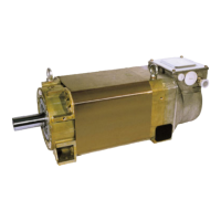
Fig. 2-9 Power Management Module (DC–PMM)
Functions, features and technical data:
S Converting the regenerative feedback energy using an integrated
pulsed resistor with i
2
t monitoring
S Regenerative feedback protection
S Signals (e.g. ready, fault)
S Max. continuous motoring current capacity: 25 A
S Ambient temperature: 0...55 _C
S Continuous power: 10 W (DC–PMM/24V)
15 W (DC–PMM/48V)
S Maximum energy drawn: 40 Ws
Example for POSMO A – 300 W (for 75 W, then P
D
= 10 W):
For power ratings above 15 W, the components, that are above
15 W are integrated up according to the following algorithm and may
not exceed 40 Ws.
V
s
2
P
t
dt –
∫
0
T
P
D
dt E
max
= 40 Ws
∫
0
T
– Transistor on:
P
t
=
R
PMM
=
(58.5 V)
2
2 Ω
= 1711.125 W; P
D
= 15 W
Vs = switching threshold PMM 58.1...58.5 V; R
PMM
= 2 Ω
P
t
– P
D
= 1711.125 W – 15 W = 1696.125 W
⇒ increment = 1696.125 W t
– Transistor off:
P
t
= 0; P
D
= 15 W
P
t
– P
D
= – 15 W
⇒ decrement = 15 W t
Power
Management
Module
(DC PMM)
2 Installing and Connecting–Up
02.9908.0306.05
 Loading...


