2
2.2 Electrical system requirements
2-41
E Siemens AG 2013 All Rights Reserved
SIMODRIVE POSMO A User Manual (POS1) – 08/2013 Edition
– Total current through the PMM: 5 x 5 A = 25 A
– Pulse load at the pulsed resistor: 5 x 3 Ws = 15 Ws
– Continuous power through
the pulsed resistor: 15 Ws/1s = 15 W
In this application, a maximum of only 3 motors could be braked
once per second or over a longer periods of time without the I
2
t
monitoring responding and causing the unit to go into a ”fault” condi-
tion (3 x 3 Ws /1s = 9 W < 10 W).
Depending on the type of power supply, the following possibilities are
available to provide regenerative feedback protection when the motors
brake:
Non–regulated 48 V power supply (transformer, rectifier)
The regenerative feedback protection depends on the following factors:
S Effective total moment of inertia
S Coincidence factor
S Power supply used (output rating)
Regulated 48 V power supply (SITOP power)
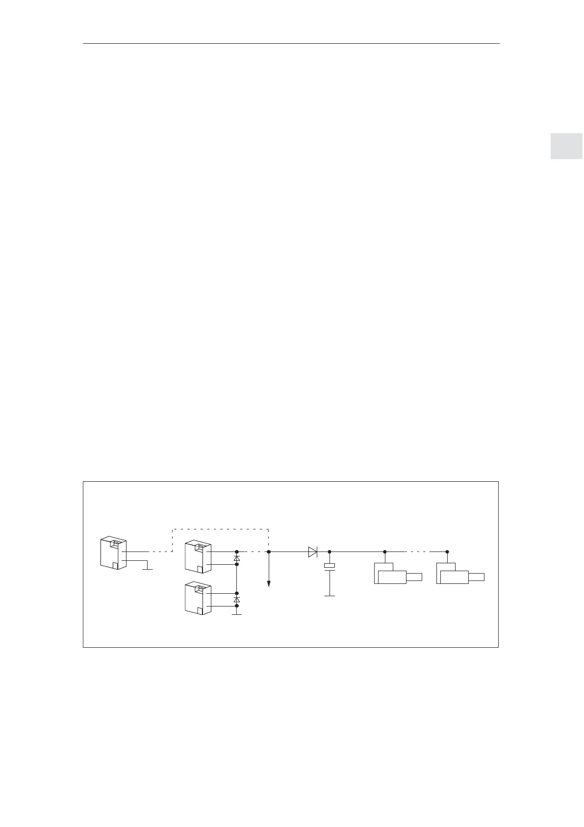
S Regenerative feedback protection with diode and capacitor
An example is shown in Fig. 2-12 where up to 3 drives can be oper-
ated under the following conditions:
– Effective overall moment of inertia = 1 motor moment of inertia
– Coincidence factor = 1
– Braking from rated speed in S3 duty
SITOP modular
48 V
L+
M
2 SITOP power
24 V
Diode (adapt the current load capacity
to SITOP, if required, use a heatsink)
Elko
15000 μF/100 V
SIMODRIVE
POSMO A, 1
SIMODRIVE
POSMO A, 3
to the
remaining
system
48 V
M
M
L+
or
Fig. 2-12 Example: Regenerative feedback protection with diode and
capacitor
Regenerative
feedback
protection for
48 V supply
(300 W motor)
2 Installing and Connecting–Up
02.9906.05