2
2.4 Mounting SIMODRIVE POSMO A
2-51
E Siemens AG 2013 All Rights Reserved
SIMODRIVE POSMO A User Manual (POS1) – 08/2013 Edition
2.4 Mounting SIMODRIVE POSMO A
2.4.1 Mounting overview
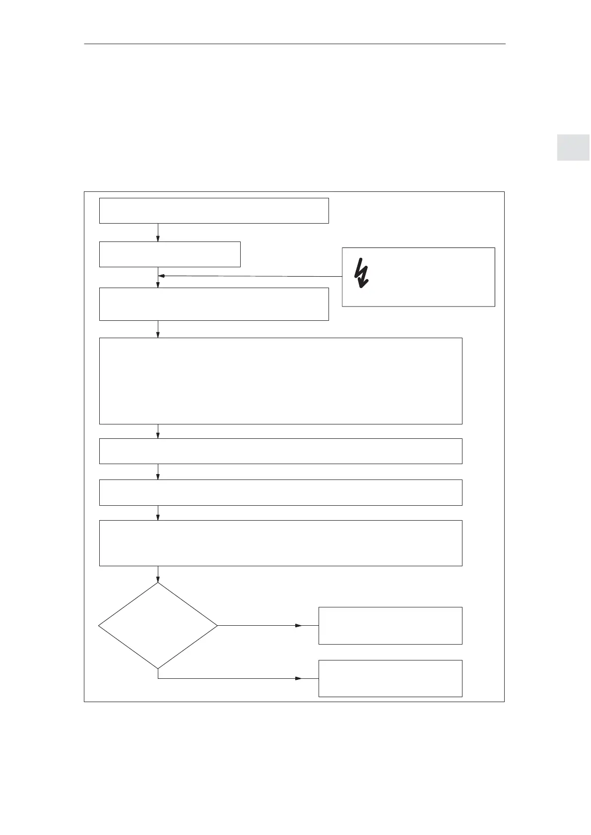
The following steps are required when mounting a SIMODRIVE POSMO A:
LED?
dark?
or
red steady light?
yes
no
Warning:
Protect an open drive
against dirt
Release the SIMODRIVE
POSMO A connection cover
Troubleshooting/diagnostics
––> Refer to Chapter 6
Locate the connection cover on the SIMODRIVE POSMO A and tighten the 2 screws
retaining the cover (max. tightening torque, 1.8 Nm)
Mount the SIMODRIVE POSMO A motor without
connection cover (refer to the dimension drawings in
Chapter C)
Switch–on the power supply for the load and electronics
S Load power supply (if no independent electronics power supply is present)
S Load and electronics power supply (if both of the power supplies are separate)
Commission the drive system
––> Refer to Chapter 3
Prepare the connection cover for mounting:
S Prepare the cable ––> refer to Chapter 2.4.2
S Install the cables in the connection cover ––> refer to Chapter 2.4.3
S Set the PROFIBUS node address ––> refer to Chapter 2.3.1
S Switch 8 setting OFF for PROFIBUS communications ––> refer to Chapter 2.3.1
S Set the PROFIBUS terminating resistor ––> refer to Chapter 2.3.1
Connect the protective and potential bonding conductors ––> refer to Chap. 2.3.2
Thoroughly remove all anti–corrosion agents from
the shaft end (use typical solvents)
Fig. 2-17 Mounting and installation steps
Mounting and
installation steps
2 Installing and Connecting–Up
02.9906.05