2
2.4 Mounting SIMODRIVE POSMO A
2-56
E Siemens AG 2013 All Rights Reserved
SIMODRIVE POSMO A User Manual (POS1) – 08/2013 Edition
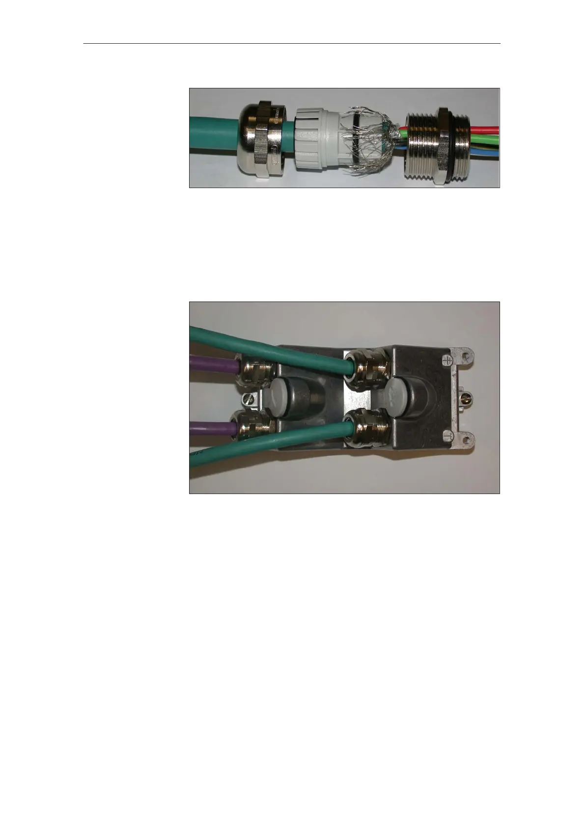
Fig. 2-25 Example: PG gland with all of the individual parts and components
The following diagrams show a connection cover that has been connected–up:
S Connection cover from the top ––> refer to Fig. 2-26
S Connection cover from the bottom ––> refer to Fig. 2-27
Fig. 2-26 Connection cover with the cables inserted: View from the top
Example:
Connection cover
mounted
2 Installing and Connecting–Up
02.9908.03