3.1 General commissioning information
3-74
E Siemens AG 2013 All Rights Reserved
SIMODRIVE POSMO A User Manual (POS1) – 08/2013 Edition
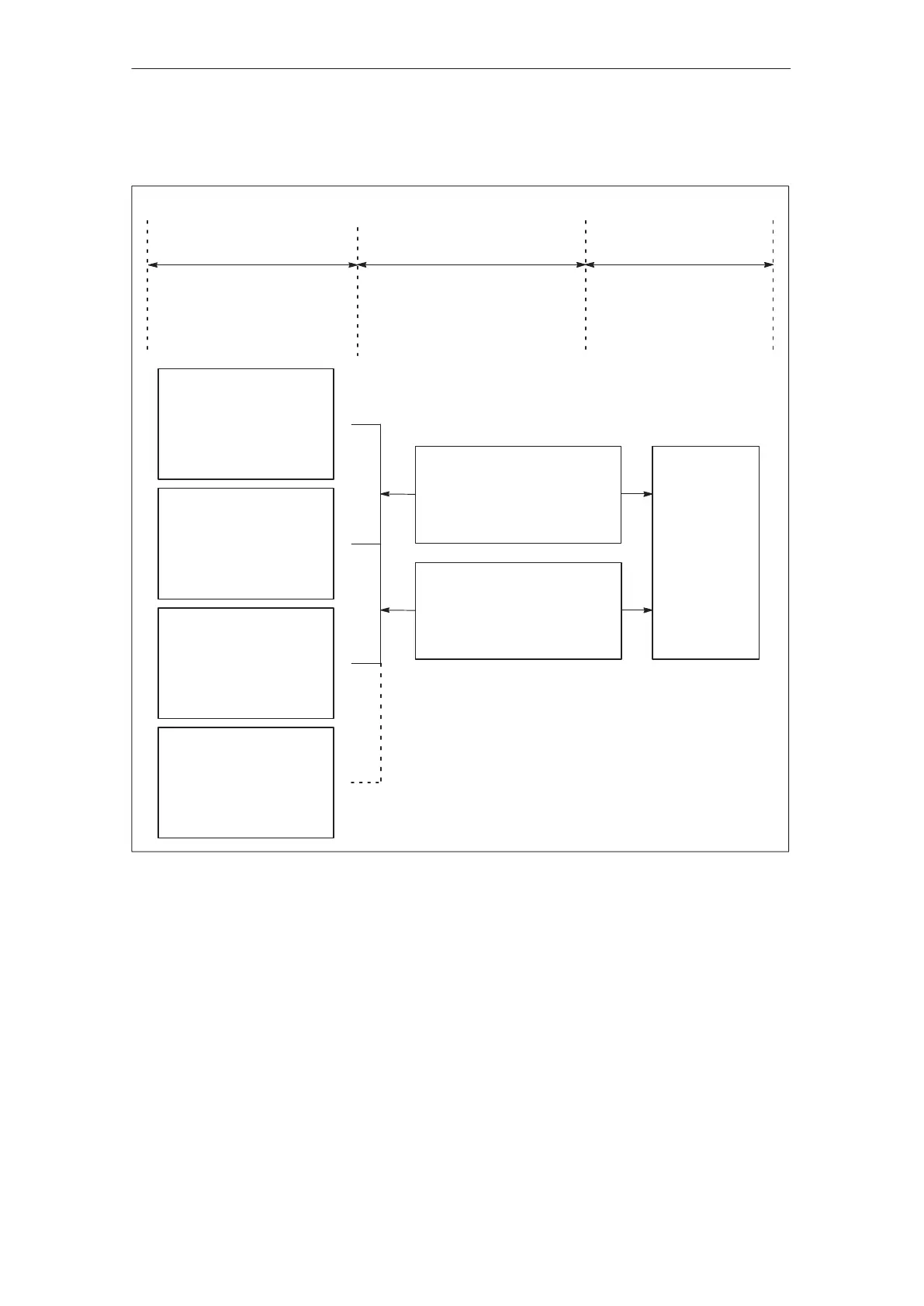
Master
PROFIBUS–DP
standard master
Slave
PROFIBUS–DP
standard slave
PROFIBUS–DP
telegram data
SIMODRIVE
POSMO A
S S7–300 with integrated
DP interface
S S7 – 400
– SFC14 (SW)
– SFC15 (SW)
S S7 – 312
S CP 342–5
– FC1 (SW)
– FC2 (SW)
S PC/PG+
– CP 5412
– CP 5511
– CP 5611
S Any third–party
master
PROFIBUS–DP
PROFIBUS–DP
S Install GSD files
S Connect–up
S Setting the address
S When required, set the
terminating resistor
Cyclic data
refer to Chapter 4.2, e.g.
S Control word (STW)
S Status word (ZSW)
Parameterizing data
refer to Chapter 4.3, e.g.
S Parameter number, Index
S parameter value
For SIMODRIVE POSMO A the
following is valid:
S PPO type 1 (PPO1)
Fig. 3-1 Overview of the communications for SIMODRIVE POSMO A
After SIMODRIVE POSMO A has been powered up, the LED has the
following status, if no fault/error has been detected:
S LED flashes green
––> bus connection is not established (refer to Chapter 6.1)
Overview of the
communications
LED after
power–on
02.99