EasyManua.ls Logo

Siemens SIMOTICS 1FT2104-4AF - Page 54

Siemens SIMOTICS 1FT2104-4AF
140 pages
Print Icon
To Next Page IconTo Next Page
To Previous Page IconTo Previous Page
Loading...
Motor components and options
4.2 Brake
1FT2 synchronous motors for SINAMICS S120
52 Configuration Manual, 03/2021, A5E50645584B AA
Motor Holding
torque
at 120 °C
Dyn. braking
torque
Rated cur-
rent
Opening
time
1)
Closing time
1)
Maximum
permissible
single oper-
ating energy
2)
Total operat-
ing energy
(service life)
M4 / Nm
M1m / Nm
In / A
t0 / ms
tc1 / ms
Wmax / J
Wtotal / kJ
For spring-loaded brake
1FT203
1.3
1.3
0.4
90
30
62
5
1FT204
3.3
3.3
0.5
110
40
270
35
For permanent-magnet brake
1FT205
8
5
0.6
90
25
570
284
1FT2106
16
9
0.7
100
50
1065
774
1FT2206
13
6.5
0.7
100
50
1550
774
1FT208-3
19
12
0.8
100
40
2000
1800
1FT208-4
1FT208-5
32
17
0.9
200
60
4800
2400
1FT210-3
32
17
0.9
200
60
6500
2400
1FT210-4
1FT210-5
55
26
1.0
220
60
8700
3800
1)
Valid for direct connection to S120 and internal switching. For external brake switching, a varistor has to be used.
2)
Maximum three EMERGENCY STOP operations in sequence, maximum 25% of all the emergency stops as high energy
stop with Wmax.
Note
If
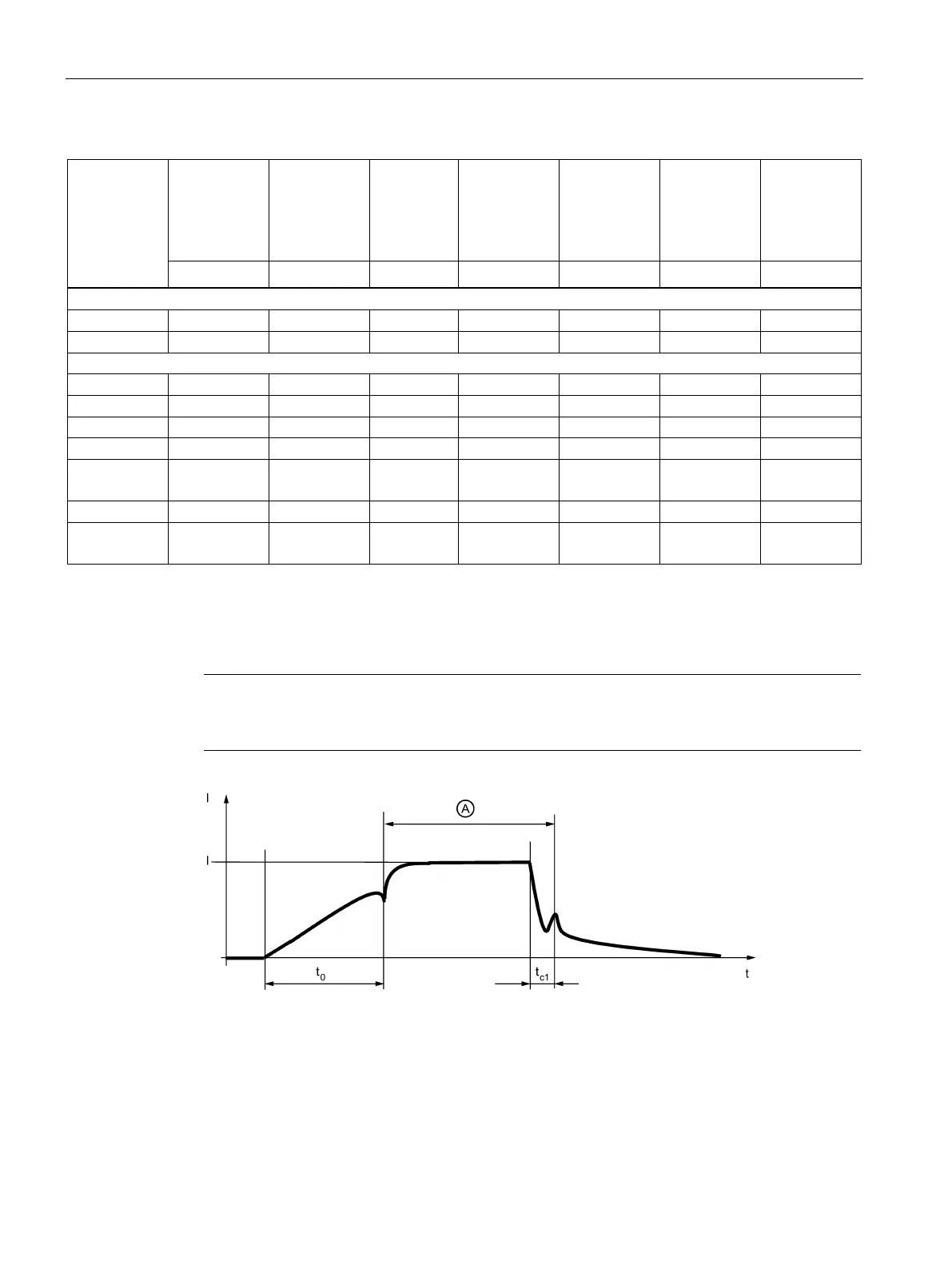
the brake is switched in two stages (two clicks), the first switching point is decisive for
opening and the second for closing.
I
Current
t
Time
t 0
Opening time
t c1
Closing time
A
Brake opened
Figure 4-1 Time-related terminology for braking operation

Table of Contents

Related product manuals