Configuration
5.4 Braking resistor (armature short-circuit braking)
1FT2 synchronous motors for SINAMICS S120
68 Configuration Manual, 03/2021, A5E50645584B AA
Calculating the braking time
The values for calculation are provided in Chapter "Data sheets and characteristics (Page 78)".
B
Tot
Br
n / r/min = operating speed
MBr / Nm = average braking torque
Tot
Mot
Ext
JTot / kgm
2
= moment of inertia
JMot / kgm
2
= motor moment of inertia
Ext
/ kgm
2
= external moment of inertia
ermining the run-on distance, consider the friction of the mechanical transmission
elements (included in the calculation as an allowance in M
B
) and the switching delay times of
the contactors.
To avoid mechanical damage to the drive, mount mechanical stops
at the e
nd of the absolute
traversing range of the machine axes.
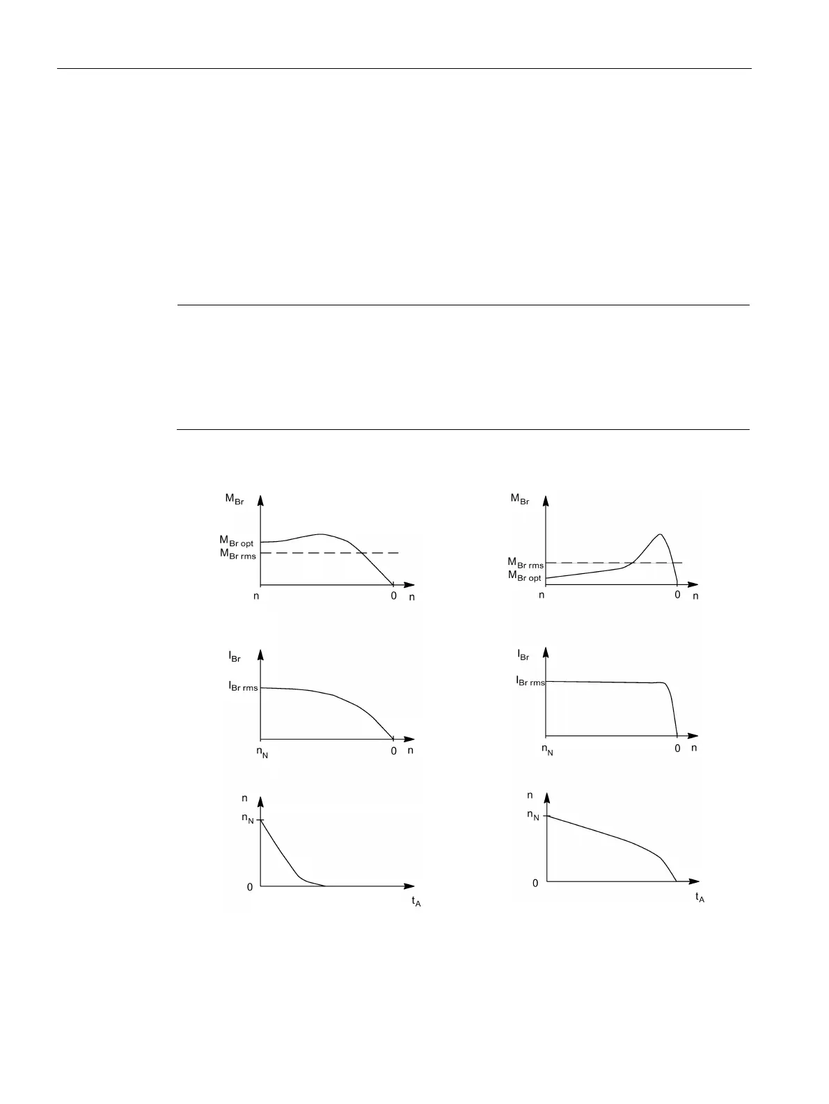
Armature short-circuit braking
with external braking resistor
without external braking resistor
IBr rms = rms braking current
MBr rms = average braking torque
MBr opt = optimum braking torque