Technical data and characteristics
6.1 Explanations
1FT2 synchronous motors for SINAMICS S120
72 Configuration Manual, 03/2021, A5E50645584B AA
Motor damage due to overheating
Continuous operation in the area above the S1 characteristic results in motor overheating
and subsequent damage.
Operate the motor within the values of the S1 characteristic.
Mmax characteristic
The M
max characteristic ② defines the operating range for transient overloads.
M
max inv characteristic
The M
max inv characteristic ③ limits the possible overload range in combination with a specific
maximum converter current. The M
max inv characteristic takes field weakening into
consideration.
n
max inv line
The mechanical variables of the motor and the properties of the converter limit the speed
range of the motor. The n
max inv line ④ limits the maximum permitted speed of the motor in a
drive system with SINAMICS S120.
Damage to the converter due to excessively high speeds
A motor speed higher than n
max inv can result in a voltage being induced in the winding that
exceeds the maximum permissible voltage at the converter. This induced voltage can
destroy the converter.
Operate the motor at speeds below n
max inv
Voltage limit characteristic curve
Field weakening starts from the voltage limit characteristic ⑤.
As the speed increases, an increasing percentage of the current is used for field weakening,
and therefore no longer generates a torque. This is the reason that the M
max characteristic
and the S1 characteristic have a steep downward gradient in the field weakening range.
Converter output voltages
Every speed-torque diagram includes different characteristics for different converter output
voltages.
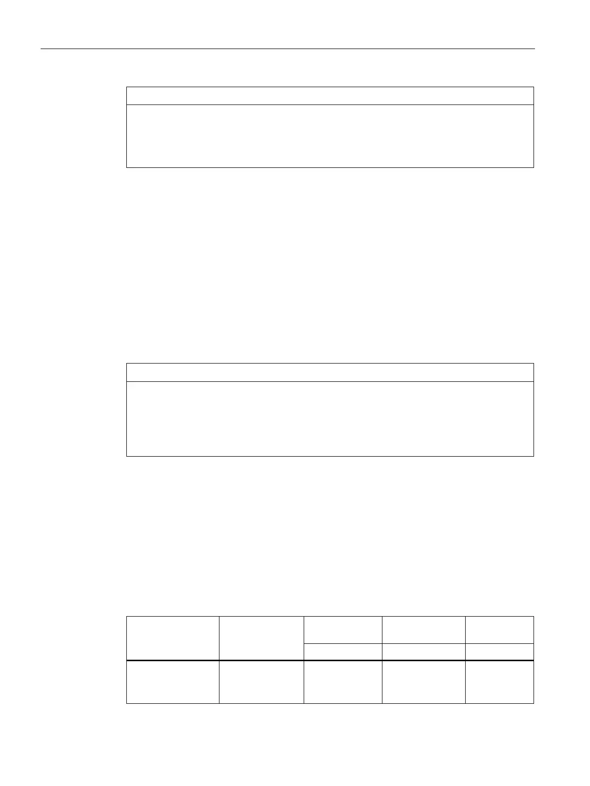
Drive system
Infeed module
Line voltage DC link voltage Output volt-
3 AC 380 V to 480 V
ALM
BLM/SLM
480 V
400 V
720 V
540 V
510 V
380 V