6.2.2.7 Minimum air clearances
After proper installation, verify that the minimum air clearances between non-insulated parts
are maintained. Be aware of any protruding wire ends.
Table 6-2 Minimum air clearance dependent on rms value of the alternating voltage U
rms
Rms value of the alternating voltage U
rms
Minimum air clearance
mm
≤250V 3.0
≤500V 3.0
≤630V 5.5
≤1000V 8.0
Values apply at an installation altitude of up to 2000m.
When determining the required minimum air clearance, the voltage value in the table may be increased by
a factor of 1.1, so that the rated input voltage range is taken into account during general use.
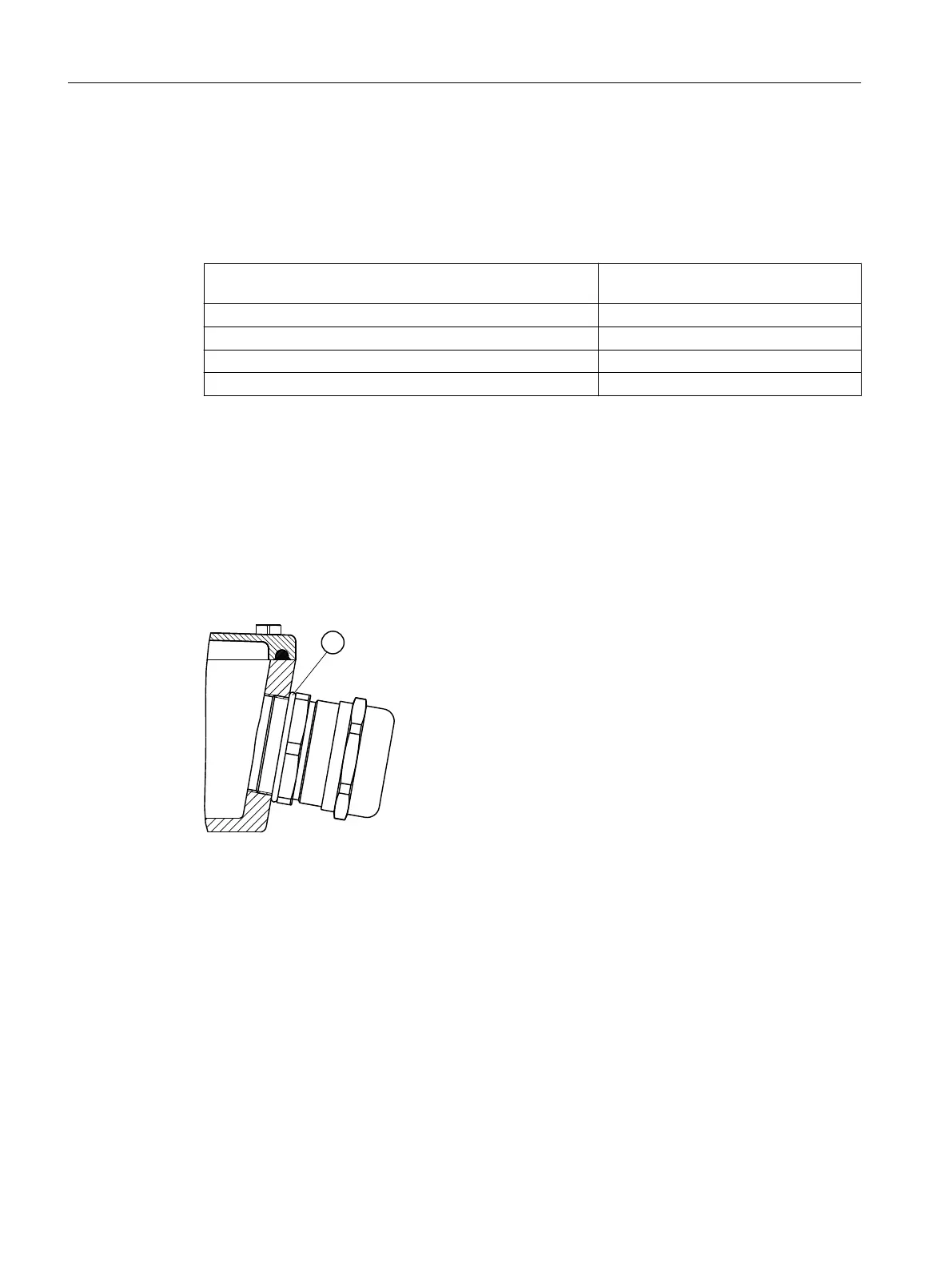
6.2.3 Screw-type connections with connecting thread
Cable glands with connecting thread in the terminal box (EN 50262)
② O ring
6.3 Tightening torques
Note the information in Chapter Tightening torques (Page133).
6.3.1 Cable entries, sealing plugs and thread adapters
Note the following when mounting:
• Avoid damaging the cable jacket.
• Adapt the tightening torques to the cable jacket materials.
Electrical connection
6.3Tightening torques
1LE5, 1PC4 shaft heights 280 ... 355
70 Operating Instructions, 11/2022, A5E41454666A