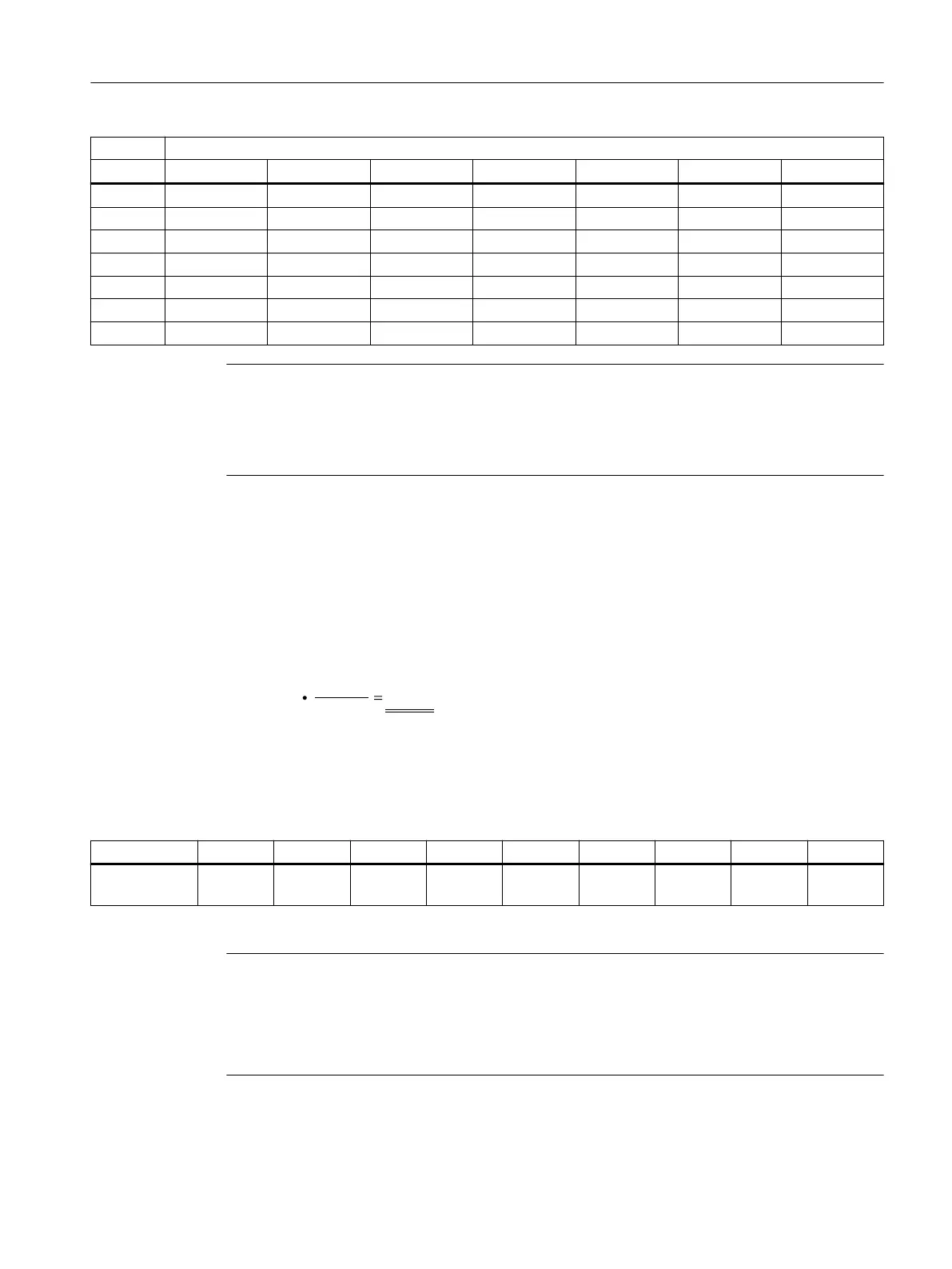
Active length in mm
30 50 70 100 110 150 200
1FW6090 - 240 330 470 - 710 -
1FW6130 - 360 500 710 - 1070 -
1FW6150 - 330 460 660 - 990 -
1FW6160 - 290 410 590 - 880 1180
1FW6190 - 350 490 710 - 1060 1410
1FW6230 - 420 590 840 - 1260 1680
1FW6290 - - 600 - 940 1280 1630
Note
It is imperative that you observe the radial forces between the stator and rotor as well as the
maximum permissible concentricity error. The maximum permissible concentricity error is
specied in the dimension drawings in the "SIMOTICS T-1FW6 built-in torque motors"
Conguration Manual.
Example
The eccentricity of a 1FW6090-0Px010-xxxx torque motor (active part length 100mm) is
0.15mm, for example.
The active radial force due to this centering error is therefore:
Axial forces between the stator and rotor
Table 5-2 Axial forces (in N) between the stator and rotor during installation
1FW6050 1FW6060 1FW6090 1FW6130 1FW6150 1FW6160 1FW6190 1FW6230 1FW6290
Axial forces
in N
40 60 80 120 150 210 250 300 450
Note
When starting to insert the rotor into the stator, the axial forces of attraction between the stator
and rotor are 4x to 5x higher.
At the end of the removal of the rotor from the stator, the axial forces of attraction between the
stator and rotor are 4x to 5x higher.
Installation
5.2Forces that occur between the stator and rotor
1FW6 built-in torque motors
Operating Instructions, 09/2022, A5E52220812B AA 69