CAUTION
Sharp edges and falling objects
Sharp edges can cause cuts and falling objects can injure feet.
• Always wear safety shoes and safety gloves!
5.2 Forces that occur between the stator and rotor
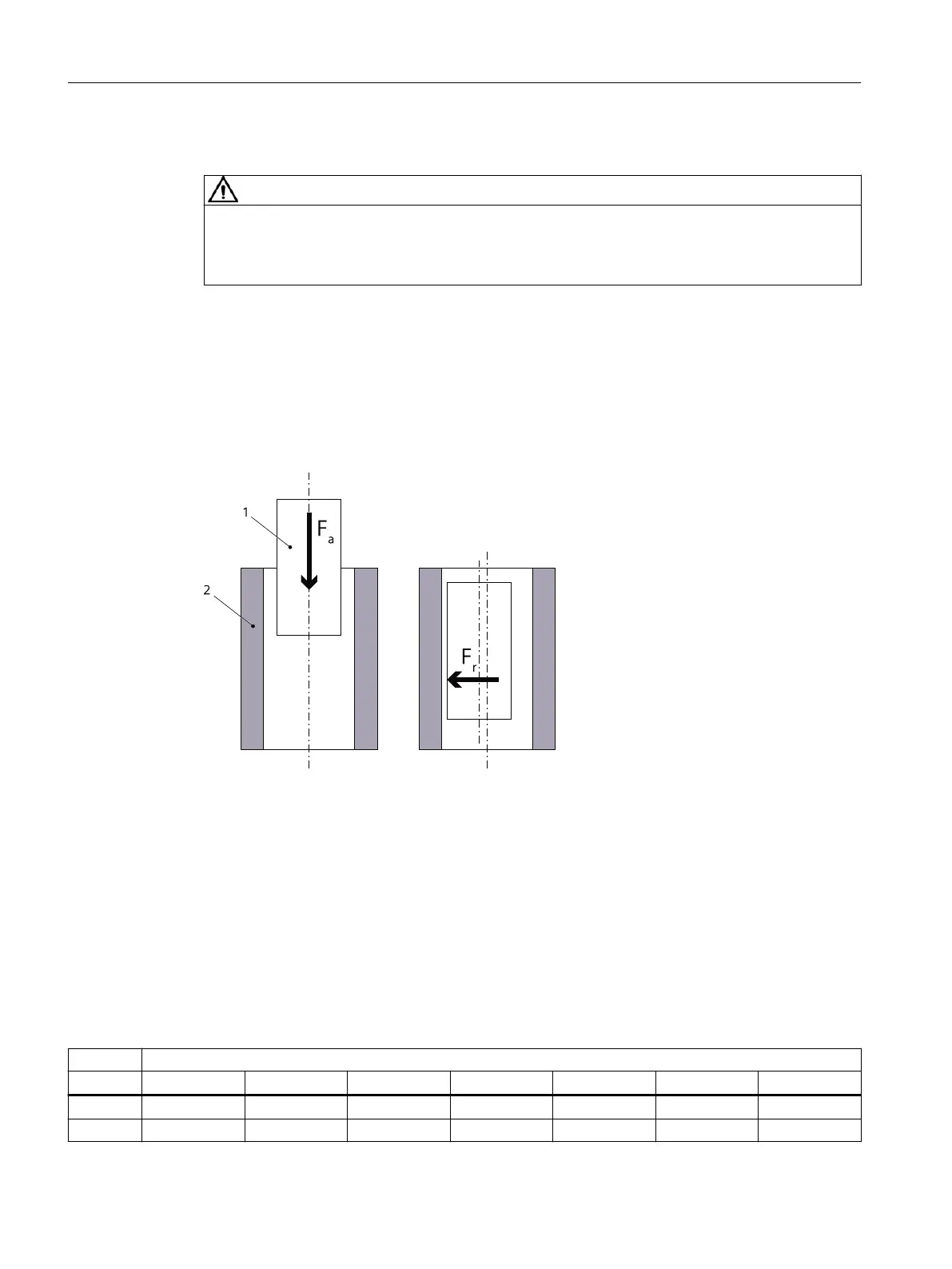
Radial and axial forces
Figure5-1 Active forces when stators and rotors are installed
1 Rotor with permanent magnets
2 Stator
F
a
Axial attractive force
F
r
Radial attractive force
Radial forces between the stator and rotor
The following table shows the active radial forces in N per 0.1 mm centering error between the
stator and rotor. The longer the active component, the greater the radial force.
Table 5-1 Radial forces in N/0.1 mm with radial centering errors during installation
Active length in mm
30 50 70 100 110 150 200
1FW6050 80 140 190 270 - 400 -
1FW6060 110 180 250 350 - 520 -
Installation
5.2Forces that occur between the stator and rotor
1FW6 built-in torque motors
68 Operating Instructions, 09/2022, A5E52220812B AA