Electrical connection
6.6 Connecting converters
1MB..5/6 shaft height 71 ... 355
80 Operating Instructions, 07/2020, A5E41926185A
6.6 Connecting converters
6.6.1 Connecting converters
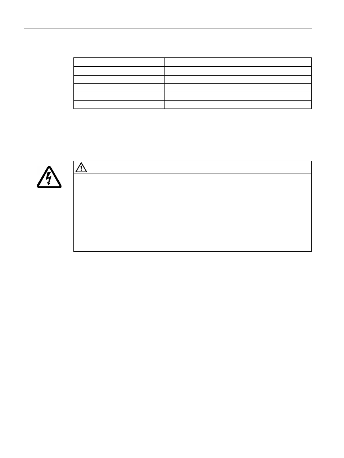
Material damage caused by an excessively high supply voltage
Material damage can occur if the supply voltage is too high for the insulation system.
Observe the values in the following tables.
SIMOTICS machines can be operated with SINAMICS G converters and SINAMICS S converters
(uncontrolled and controlled infeed) when maintaining the permissible peak voltages.
The insulation system of SIMOTICS machines corresponds to the specifications laid down in
IEC 60034-18-41 according to voltage stress category C (IVIC C = high stress).
Table 6- 5 Maximum voltage peaks at the motor terminals for line (DOL) motors, converter operation possible
V
Maximum peak voltage at the motor terminals
phase-to-phase
phase-to-ground
DC
Table 6- 6 Maximum voltage peaks at the motor terminals for motors specifically designed for converter operation (e.g.
VSD 10)
V
Maximum peak voltage at the motor terminals
phase-to-phase
phase-to-ground
DC
Depending on the step height, the voltage rise times for the individual voltage steps in the
line-to-ground voltage at the motor end of the cable must not fall below the following values.
Table 6- 7 Rise times as a function of voltage level
r