Configuring and installing
4.2 Configuring an installation using SIMOTION C modules
SIMOTION C
82 Operating Instructions, 02/2012
4.2.5 Layout of modules on several racks
Overview
With the SIMOTION C, a 2-tier layout is possible.
Interface modules
Interface modules are required for the 2-tier layout which route the backplane bus from one
rack to the other. The SIMOTION C is always located on rack 0.
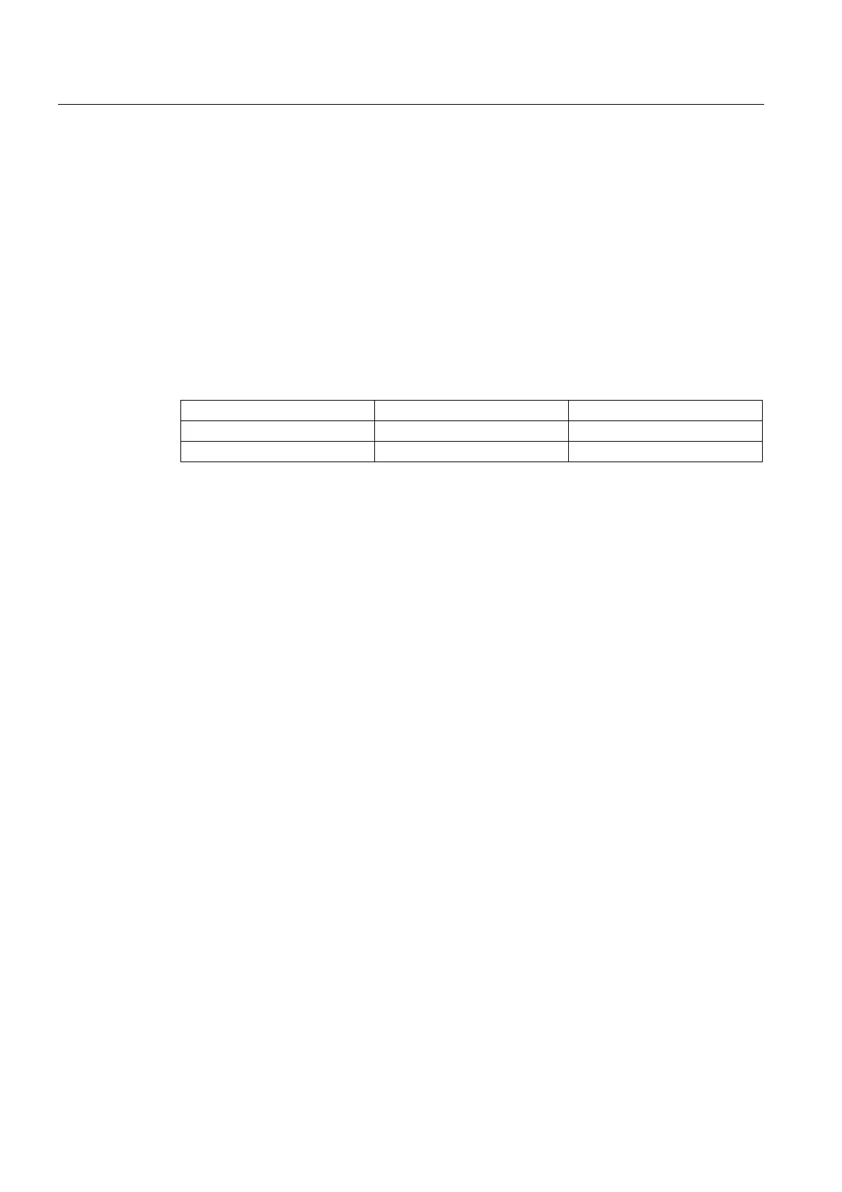
Table 4- 3 Interface modules
Interface module Usable for ... Order number
IM 365 SEND Rack 0 6ES7 365-0BA01-0AA0
IM 365 RECEIVE Rack 1
IM 365 interface modules
The two IM 365 interface modules have a fixed connection via a 1-meter long connecting
cable.
The total power consumption of the inserted I/O modules of both racks must not exceed 1.2
A; the power consumption from rack 1 is limited to 800 mA.
Rules
The following rules apply with respect to the layout of the modules on two racks:
● The interface module always occupies Slot 3 and is always left of the first signal module.
● No more than eight modules may be inserted per rack. These modules are always to the
right of the interface modules.
● The number of inserted modules is limited by the permissible power consumption from
the backplane bus. Total power consumption must not exceed 1.2 A (see Technical data
table for each module in the manual
S7-300 Automation System, M7-300 Module Data
).