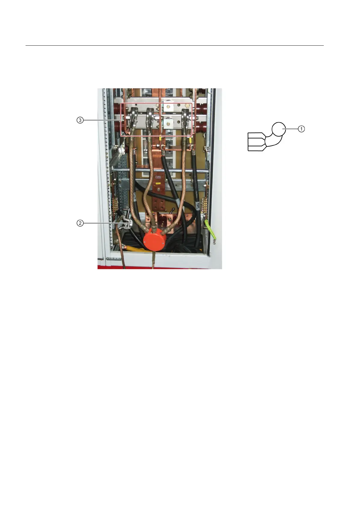
The diagram shows the method of attaching the grounding spider. Secure the clamps for the
grounding spider to the ball heads ② and ③ in the cabinet.
① Schematic diagram of ball head
② Ball head
③ Ball head
Figure 9-1 Schematic diagram for attaching the grounding spider
A motor-operated grounding switch is incorporated into the system for the purpose of
grounding it. To ground the system, press the button labeled
<EARTHING SWITCHES CLOSE> on the power unit to close the make-proof grounding switch.
A motor-operated disconnector/grounding switch is incorporated into the system for the
purpose of grounding and isolating it. To ground and isolate the system, proceed as follows:
● To open the disconnector, press the button labeled <DISCONNECTORS OPEN> on the
power unit.
● To close the make-proof grounding switch, press the button labeled
<EARTHING SWITCHES CLOSE> on the power unit.
Maintenance
9.2 Grounding the system
SINAMICS GL150 6SL38555UN113KA0Z
124 Operating Instructions Rev.201910281450 EXAMPLE

 Loading...


