Parameter list
7.2 Parameter list
SINAMICS V20 Inverter
Operating Instructions, 07/2012, A5E03728167
219
Parameter Function Range Factory
default
Can be
changed
Scaling Data
set
Data
type
Acc.
Level
r2848.0 BO: NOT-Q RS-FF 3 - - - - - U16 3
Displays Not-output of RS-FlipFlop 3, inputs are defined in P2846[0], P2846[1]. See r2811 for the bit field
description.
Dependency: See P2846
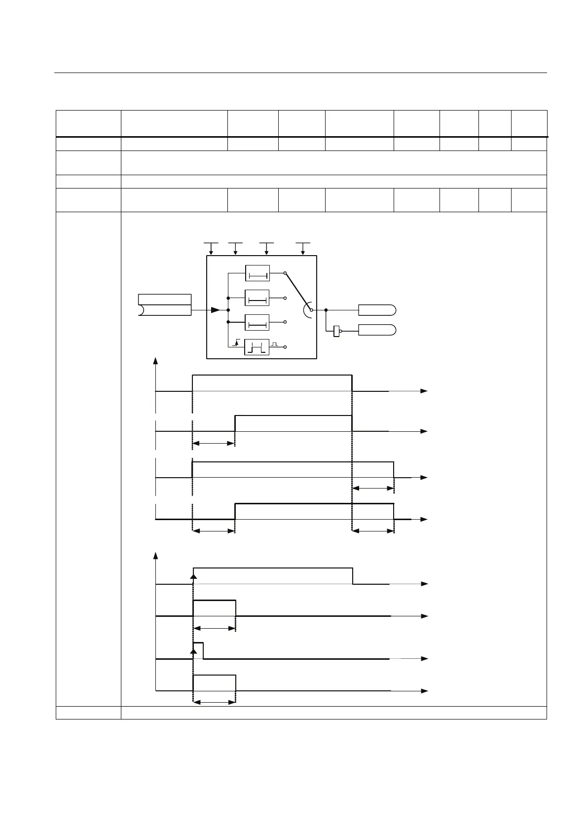
P2849 BI: Timer 1 - 0 U, T - - U32 /
Bin
3
Define input signal of timer 1. P2849, P2850, P2851 are the inputs of the timer, outputs are r2852, r2853.
T
0
0T
TT
r2852
1
r2853
P2849
P2851(0)
P2850 (0.000)
P2850
t
t
t
t
P2850 P2850
P2850
P2850
t
t
t
t
P2850
P2800
P2802.0
P2851 = 0
P2851 = 1
P2851 = 2
P2851 = 3
T
,QGH[
'HOD\7LPH
21'HOD\
2))'HOD\
212))'HOD\
3XOVH*HQHUDWRU
0RGH
,Q
,Q
,Q
,Q
2XW
2XW
2XW
2XW
12XW
(ON Delay)
(OFF Delay)
(ON-OFF Delay)
(Pulse Generator)
Dependency: P2802[0] assigns the timer to the processing sequence.

 Loading...


