PLC Subroutines Manual
32 6FC5397-0FP40-0BA0, 08/2013
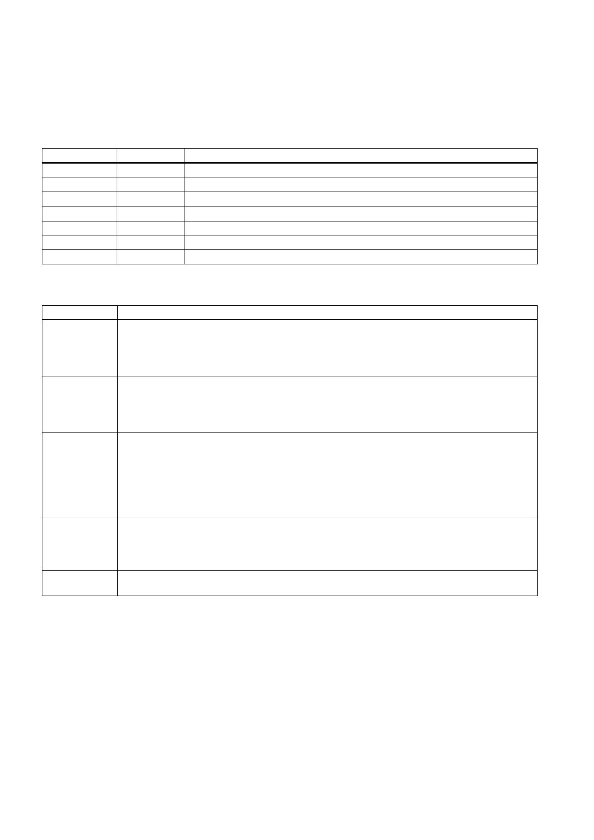
Table 3-1 USER_DATA_INT
14510 [12] - Layout of the traverse keys
14510 [13] 0.1s Time for spindle braking
14510 [20] - The maximum number of tool bits
14510 [21] 0.1s Turret clamping time
14510 [22] 0.1s Monitoring time for searching a tool
14510 [24] 1 min Lubricating intervals
14510 [25] 0.01s Lubricating duration
Table 3-2 USER_DATA_HEX
14512 [16] Bit 1: function of chip remover (milling)
Bit 2: function of safe door (milling)
Bit 3: when the function of safe door is active, it can be triggered by M01/M02 (milling).
Bit 7: handwheel assignment with the MCP / HMI
14512 [17] Bit 0: turret (turning); tool magazine (milling)
Bit 1: clamping function (turning)
Bit 2: tail stock function (turning)
Bit 3: selection between handwheel and hand-held unit (0: handwheel; 1: hand-held unit)
14512 [18] Special configurations for a machine
Bit 2: automatic lubrication after first power-on (factory setting)
Bit 4: signal that external spindle stops
Bit 5: spindle positioning direction
Bit 6: the hardware limit is independent from a PLC program
Bit 7: each feed axis has a hardware limit switch (activated when Bit 6 = 0)
14512 [19] Bit 1: function of spindle braking
Bit 2: password clearing by power-on (0: delete the password; 1: do not delete the password)
Bit 7: manual machine function (this function become active if you have installed licensed turning
machine system and called it with a PLC subroutine)
14512 [20] Bit 1: Spindle disable mode (0: disable by pressing the spindle stop key; 1: disable when detecting the
standstill speed)
1)
1)
When setting bit 1 to
, make sure that the speed control mode is active.
Conventions for the symbols used in the subroutines
The symbols used in the subroutines follow the conventions listed below:
● Leading characters designate the destinations of interface signals
– P_: to PLC interface
– H_: to HMI interface
– N_: to NCK interface
– M_: to MCP interface