PLC Subroutines Manual
6FC5397-0FP40-0BA0, 08/2013
71
14510[24] Lubrication interval (in 1min)
14510[25] Lubrication duration (in 0.01s)
14512[16] Bit 7 Handwheel assignment with the MCP / HMI
14512[17] Bit 0 Turret function
Bit 1 Clamping function
Bit 2 Tailstock function
Bit 3 Selection between handwheel and hand-held unit (0: handwheel; 1: hand-held unit)
14512[18] Bit 2 One time automatic lubrication after the power-on
Bit 4 Stop signal for an external spindle
Bit 5 Fixing the direction of a spindle
Bit 6 Hardware limit is independent of the PLC application
Bit 7 One hardware limit triggered per axis (enabled when bit 6=0)
14512[19] Bit 1 Function of spindle braking
Bit 2 Password clearing by power-on (0: delete the password; 1: do not delete the password)
Bit 7 MM+ (Manual Machine Plus) function (enabled when the MM+ has been licensed and
corresponding PLC subroutine has been called)
14512[20] Bit 1 Spindle disable mode
PLC sample application (milling)
This sample application is applicable to machines with the following configurations:
● Three axes: axes X, Y and Z, with a hardware limit switch respectively in the positive and negative directions of each axis
● An analog spindle: SP (the fourth axis)
● PLC-controlled timely and quantitatively lubrication system
● PLC-controlled cooling system
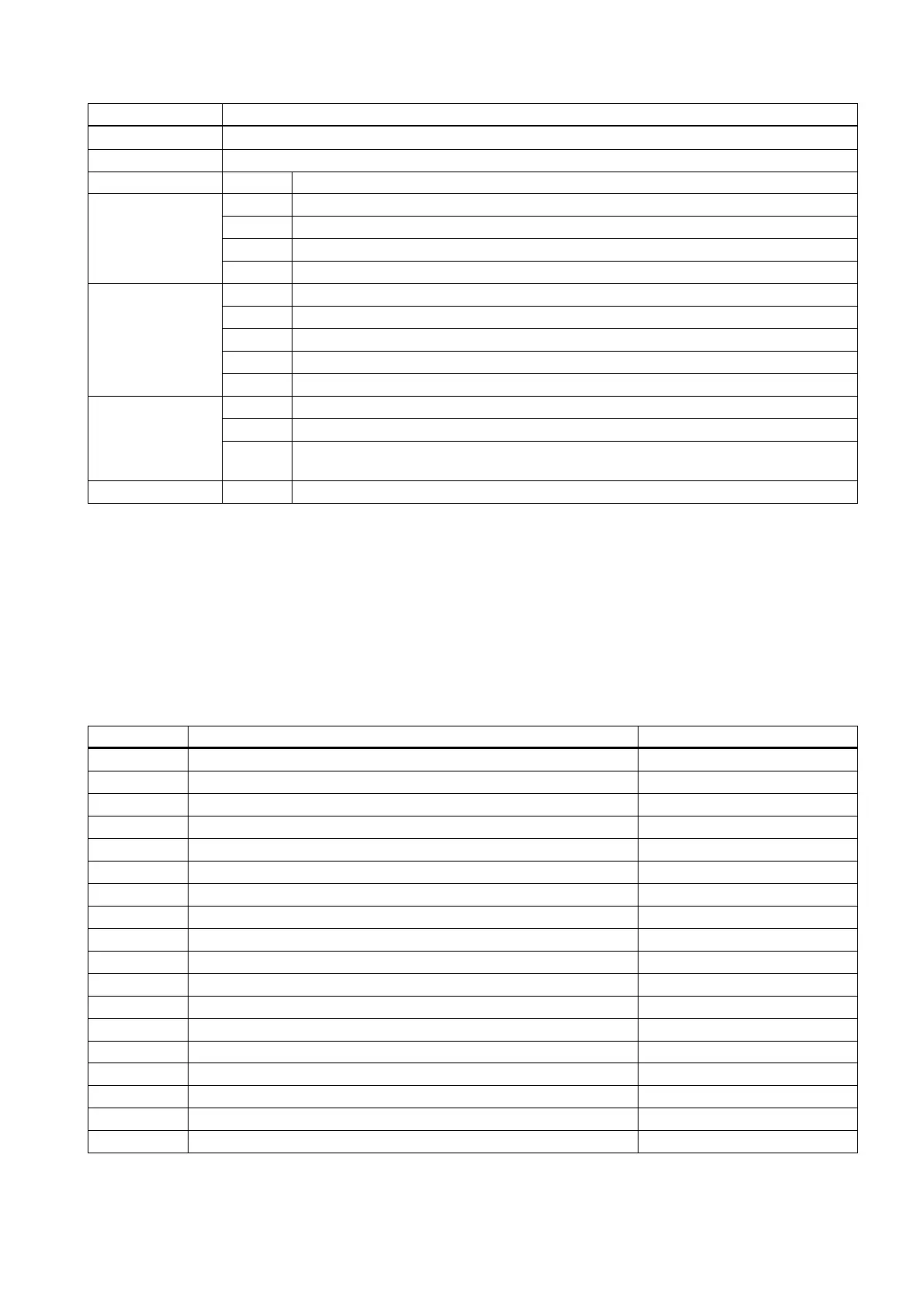
Table 5-3 Assignment of inputs and outputs
I0.0 Emergency Stop button Normally closed
I0.1 Limit switch in the "+" direction of axis X Normally closed
I0.2 Limit switch in the "-" direction of axis X Normally closed
I0.3 Limit switch in the "+" direction of axis Y
I0.4 Limit switch in the "-" direction of axis Y
I0.5 Limit switch in the "+" direction of axis Z Normally closed
I0.6 Limit switch in the "-" direction of axis Z Normally closed
I0.7 Reference point switch of axis X Normally open
I1.0 Reference point switch of axis Y
I1.1 Reference point switch of axis Z Normally open
I1.2 Disk-style tool magazine: tool magazine count Valid at a low level
I1.3 Disk-style tool magazine: tool magazine at the spindle position Valid at a low level
I1.4 Disk-style tool magazine: tool magazine at the original position Valid at a low level
I1.5 Disk-style tool magazine: tool at the release position Valid at a low level
I1.6 Disk-style tool magazine: tool at the clamping position Valid at a low level
I1.7 Valid at a low level
I2.0 Normally closed
I2.1 Reserved
 Loading...


