5.2.4.5 In the basic unit with Inductive Limit Switches (ILS) 6DR4004-6G/-8G (-Z D56)
You have a positioner with order suffix -Z order code D56. In this version of the positioner, the
digital outputs A1 and A2 of the Inductive Limit Switches (ILS) are electrically connected to the
M12 device plug.
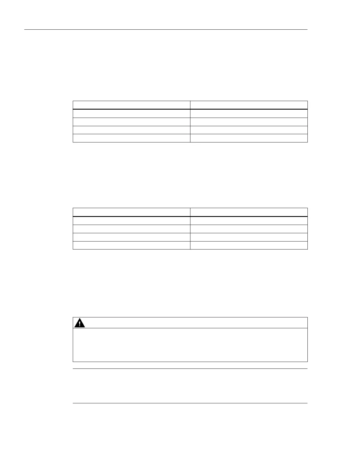
Table 5-5 Assignment diagram
Terminal of digital outputs A1 and A2 Pole designation
41 (+) 1 - Brown
52 (-) 4 - Black
42 (-) 3 - Blue
51 (+) 2 - White
5.2.4.6 In the basic unit with Mechanic Limit Switches (MLS) 6DR4004-6K (-Z D57)
You have a positioner with order suffix -Z order code D57. In this version of the positioner, the
digital outputs A1 and A2 of the Mechanic Limit Switches (MLS) are electrically connected to
the M12 connector.
Table 5-6 Assignment diagram
Terminal of digital outputs A1 and A2 Pole designation
41 (+) 1 - Brown
52 (-) 4 - Black
42 (-) 3 - Blue
51 (+) 2 - White
5.3 Pneumatic connection
5.3.1 Basic safety instructions for the pneumatic connection
WARNING
Supply pressure PZ
For safety reasons, the supply pressure PZ can be fed after installation only if the positioner
is switched to "P-Manual mode" when an electrical signal is present. This operating mode is
preset in the delivery state.
Note
Specifications regarding air quality
Observe the specifications regarding the air quality in section "Technical specifications
> Pneumatic data (Page 239)".
Connection
5.3 Pneumatic connection
SIPART PS2 with 4 to 20 mA/HART
90 Operating Instructions, 11/2019, A5E00074631-AE
 Loading...


