2.5 Distance Protection
155
7SD5 Manual
C53000-G1176-C169-1
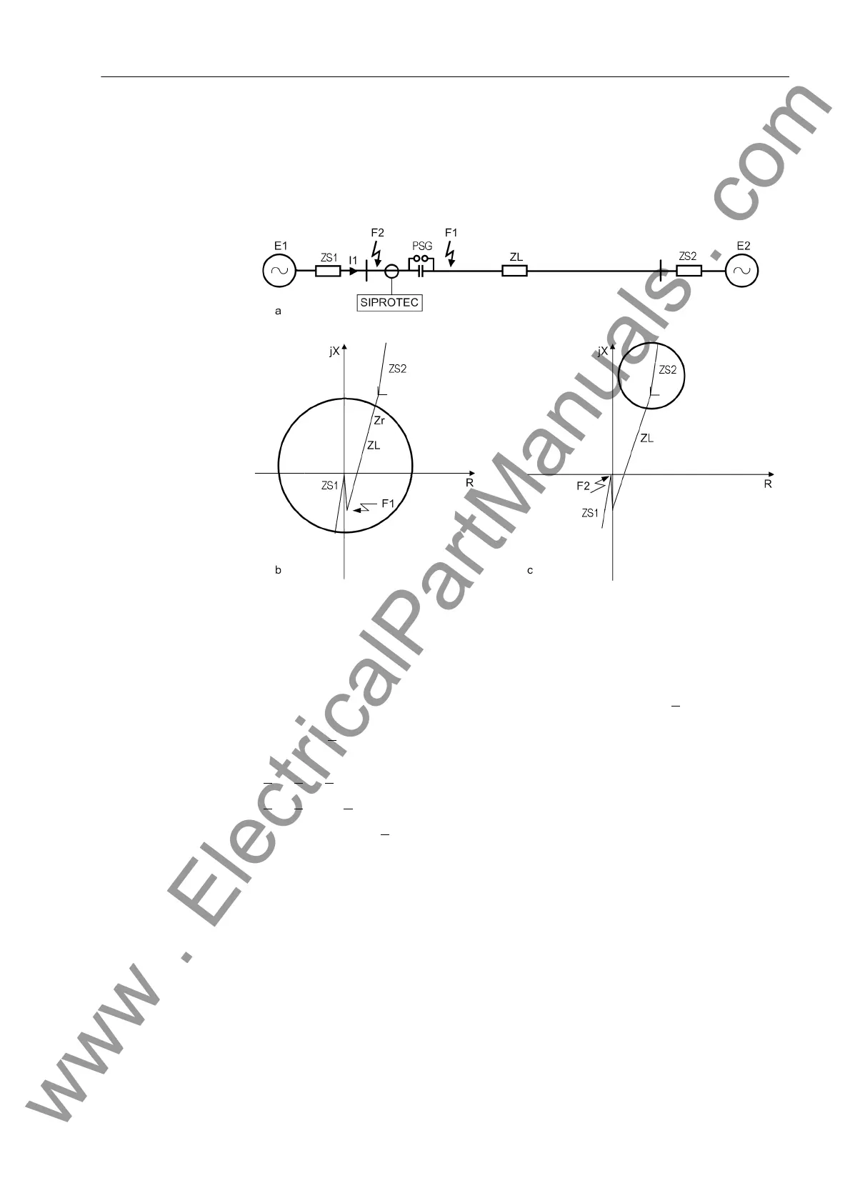
If the short-circuit is located before the capacitor, from the relay location (current trans-
former) in reverse direction, the zeniths of the MHO characteristic are shifted to the
other direction (Figure 2-52c). A correct determination of the direction is thus also
ensured in this case.
Figure 2-52 Polarized MHO characteristic for series-compensated lines
Assignment to Trip-
ping Zones and
Zone Pickup
The assignment of measured values to the tripping zones of the MHO characteristic
is done for each zone by determining the angles between two differential phasors ∆Z
1
and ∆Z
2
(Figure 2-53). These phasors result from the difference between the two
zeniths of the circle diameter and the fault impedance. The zenith Z
r
corresponds to
the set value for the zone under consideration (Z
r
and ϕ
MHO
as shown in Figure 2-48),
the zenith kZ
V
corresponds to the polarizing magnitude. Therefore the difference
phasors are
∆Z
1
= Z
F
– Z
r
∆Z
2
= Z
F
– k · Z
S
In the limiting case, Z
F
is located on the perimeter of the circle. In this case the angle
between the two difference phasors is 90° (Thales-theorem). Inside the characteristic
the angle is greater than 90° and outside the circle it is less than 90°.
www . ElectricalPartManuals . com
 Loading...


