2 Functions
272
7SD5 Manual
C53000-G1176-C169-1
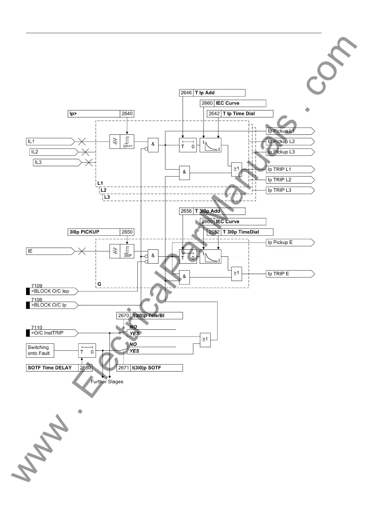
The following figure shows the logic diagram. The setting parameter addresses of the
IEC characteristics are shown by way of an example. In the setting information (Sec-
tion 2.14.3) the different setting addresses are elaborated upon.
Figure 2-118 Logic diagram of the I
P
-stage (inverse time overcurrent protection), for example IEC characteristic
Additional Stage
I>>>
The additional definite time or instantaneous overcurrent stage I-STUB has an extra
enable input (Figure 2-119). It is therefore also suitable e.g. as an emergency stage.
The enable input „>I-STUB ENABLE“ can be assigned to the output signal „Emer.
mode“ (either via binary outputs and inputs or via the user-definable logic CFC func-
tions). The stage is then automatically active when the differential protection is not ef-
fective due to a data disturbance, and the distance protection due to a failure of the
measuring voltage.
www . ElectricalPartManuals . com
 Loading...


