2.14 Backup Time Overcurrent Protection
271
7SD5 Manual
C53000-G1176-C169-1
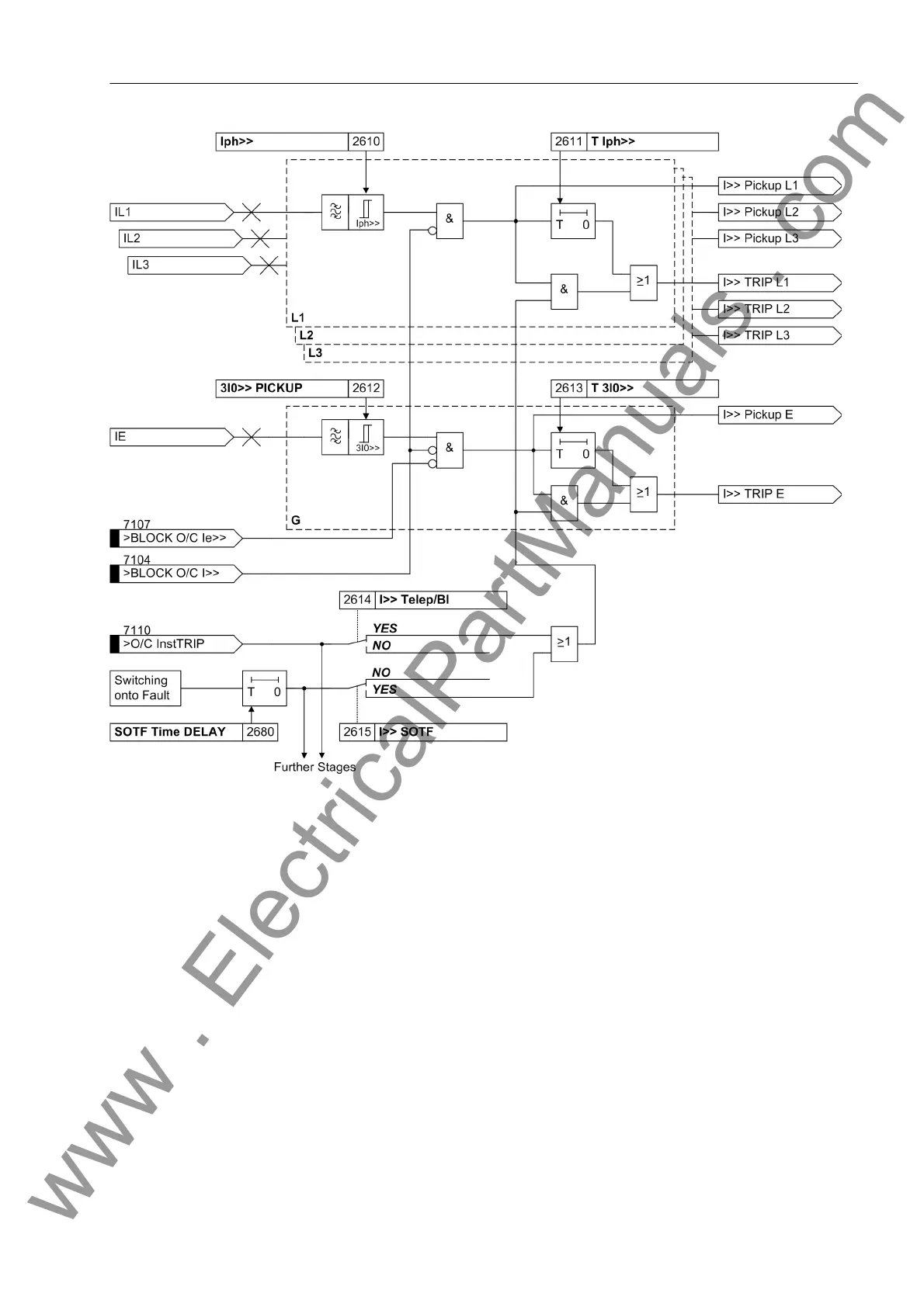
Figure 2-117 Logic diagram of the I>> stage
In addition, the earth current stage can be blocked separately via the binary input
„>BLOCK O/C Ie>>“, e.g. during a single-pole dead time before reclosure in order
to avoid a spurious tripping with the zero phase-sequence system which is present
then.
Definite Time Over-
current Stage I>
The logic of the overcurrent stage I is the same as that of the I>> stages. In all refer-
ences Iph>> must merely be replaced with Iph> or 3I0>> PICKUP with 3I0>. In all
other respects Figure 2-117 applies.
Inverse Time Over-
current Stage I
P
The logic of the inverse overcurrent stage also operates chiefly in the same way as
the remaining stages. However, the time delay is calculated here based on the type of
the set characteristic, the intensity of the current and a time multiplier (following fig-
ure). A pre-selection of the available characteristics was already carried out during the
configuration of the protection functions. Furthermore, an additional constant time
delay T Ip Add or T 3I0p Add may be selected, which is added to the inverse time.
The possible characteristics are shown in the Technical Data.
www . ElectricalPartManuals . com
 Loading...


