2 Functions
326
7SD5 Manual
C53000-G1176-C169-1
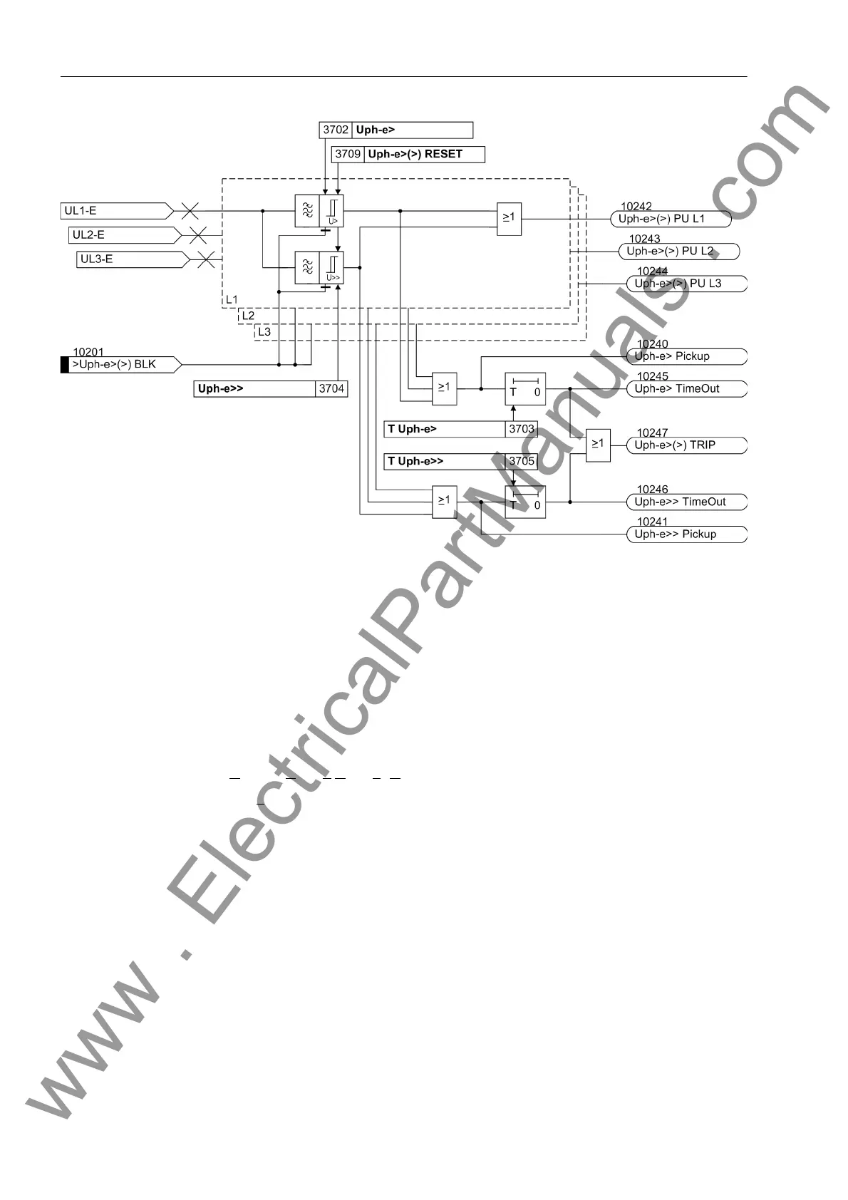
Figure 2-132 Logic diagram of the overvoltage protection for phase voltage
Phase-phase Over-
voltage
The phase–phase overvoltage protection operates just like the phase–earth protection
except that it detects phase–to–phase voltages. Accordingly, phase–to–phase voltag-
es which have exceeded one of the stage thresholds Uph-ph> or Uph-ph>>are also
indicated. Beyond this, Figure 2-132 applies in principle.
The phase–phase overvoltage protection can also be blocked via a binary input
„>Uph-ph>(>) BLK“.
Overvoltage Posi-
tive Sequence
System U
1
The device calculates the positive sequence system according to its defining equation
U
1
=
1
/
3
·(U
L1
+ a·U
L2
+ a
2
·U
L3
)
where a
= e
j120°
.
The resulting single–phase AC voltage is fed to the two threshold stages U1> and
U1>> (see Figure 2-133). Combined with the associated time delays T U1> and T
U1>> these stages form a two-stage overvoltage protection for the positive sequence
system. Here too, the drop-out to pickup ratio can be set.
The overvoltage protection for the positive sequence system can also be blocked via
a binary input „>U1>(>) BLK“.
www . ElectricalPartManuals . com
 Loading...


