2 Functions
328
7SD5 Manual
C53000-G1176-C169-1
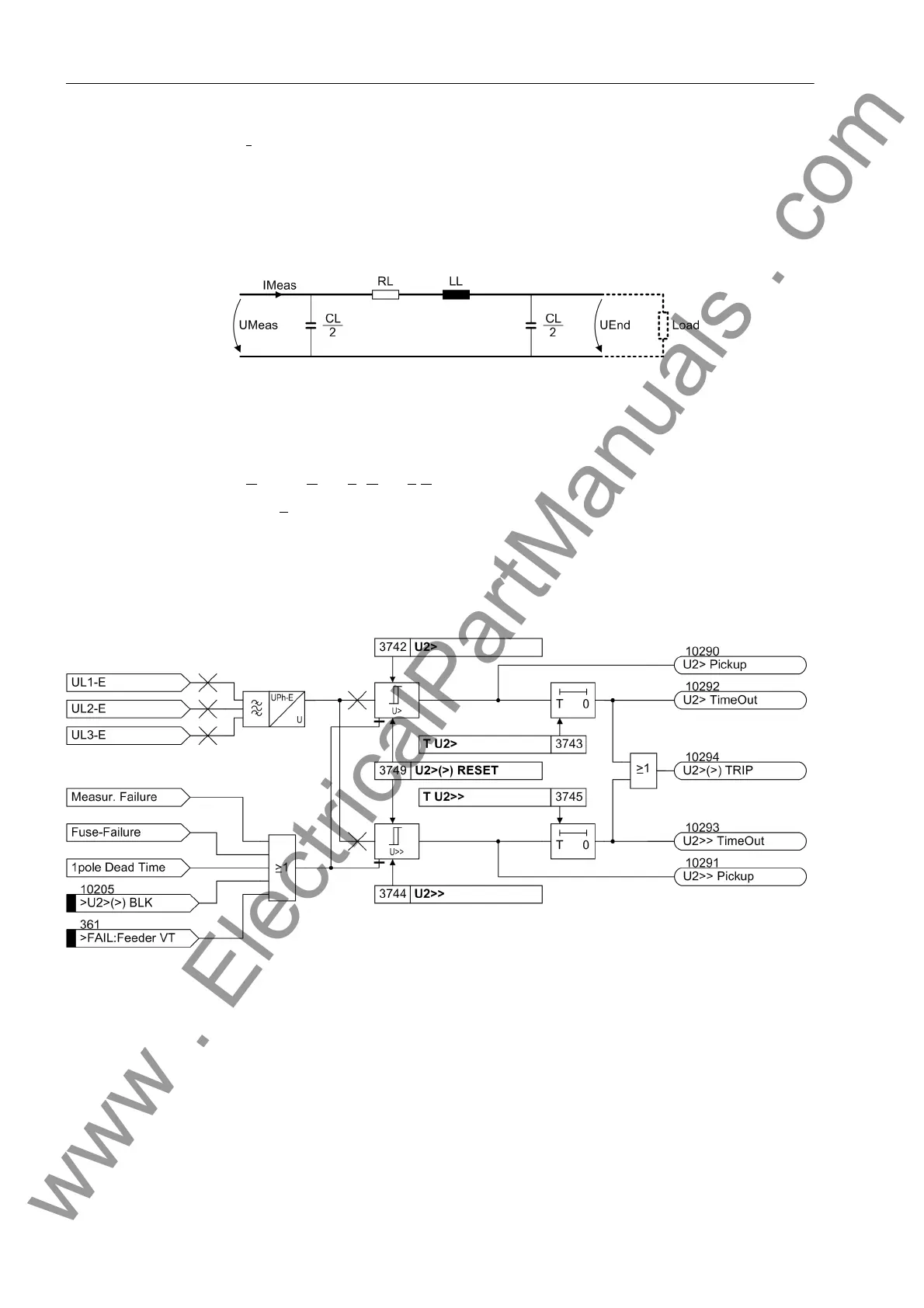
I
Meas
the measured current at the local line end,
C
L
the line capacitance,
R
L
the ohmic line resistance,
L
L
the line inductance.
Figure 2-134 PI equivalent diagram for compounding
Overvoltage Nega-
tive Sequence
System U
2
The device calculates the negative sequence system voltages according to its defining
equation:
U
2
=
1
/
3
·(U
L1
+ a
2
·U
L2
+ a·U
L3
)
where a
= e
j120°
.
The resulting single–phase AC voltage is fed to the two threshold stages U2> and
U2>>. Figure 2-135 shows the logic diagram. By combining the associated time delays
T U2> and T U2>> a two-stage overvoltage protection for the negative sequence
system is formed. Here too, the drop-out to pickup ratio can be set.
Figure 2-135 Logic diagram of the overvoltage protection for the negative sequence voltage system U
2
The overvoltage protection for the negative sequence system can also be blocked via
a binary input „>U2>(>) BLK“. The stages of the negative sequence voltage protec-
tion are automatically blocked as soon as an asymmetrical voltage failure was detect-
ed („Fuse–Failure–Monitor“, also see Section 2.22.1, margin heading „Fuse Failure
Monitor (Non-symmetrical Voltages))“ or when the trip of the mcb for voltage trans-
formers has been signalled via the binary input „>FAIL:Feeder VT“ (internal indi-
cation „internal blocking“).
www . ElectricalPartManuals . com
 Loading...


