2.20 Circuit Breaker Failure Protection
369
7SD5 Manual
C53000-G1176-C169-1
choice is made in address 3903 1p-RETRIP (T1). Set this parameter to YES if you
wish single-pole trip for the first stage, otherwise to NO.
If the breaker does not respond to this trip repetition, the adjacent circuit breakers are
tripped after T2, i.e. the circuit breakers of the busbar or of the concerned busbar
section and, if necessary, also the circuit breaker at the remote end unless the fault
has been cleared.
Separate delay times can be set
• for single- or three-pole trip repetition to the local feeder circuit breaker after a 1-
pole trip of the feeder protection T1-1pole at address 3904,
• for three-pole trip repetition to the local feeder circuit breaker after 3-pole trip of the
feeder protection T1-3pole (address 3905),
• for trip of the adjacent circuit breakers (busbar zone and remote end if applicable)
T2 at address 3906.
The delay times are set dependant on the maximum operating time of the feeder
circuit breaker and the reset time of the current detectors of the breaker failure protec-
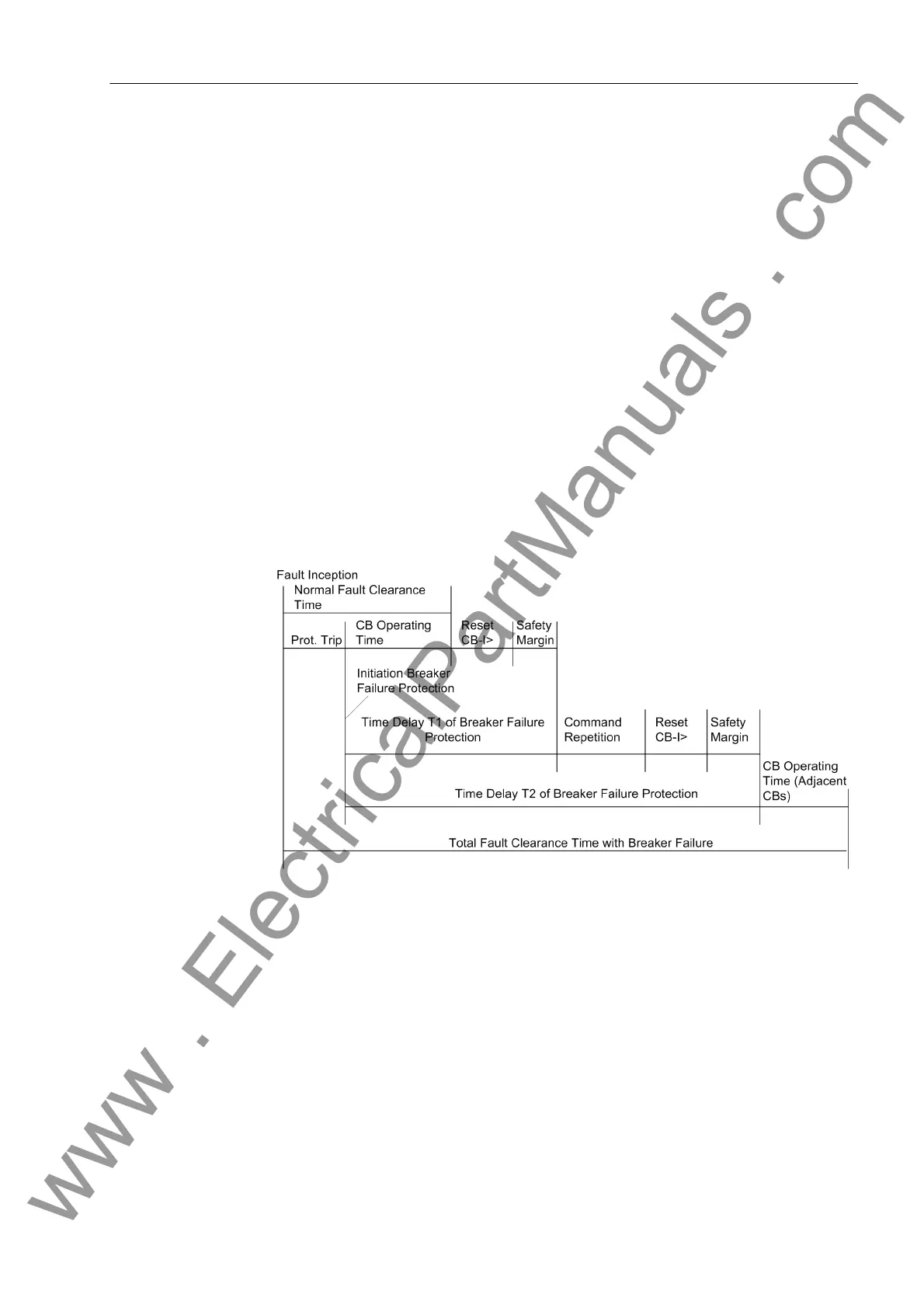
tion, plus a safety margin which allows for any tolerance of the delay timers. Figure 2-
159 illustrates the timing of a typical breaker failure scenario. The dropout time for si-
nusoidal currents is ≤ 15 ms. If current transformer saturation is anticipated, the time
should be set to 25 ms.
Figure 2-159 Time sequence example for normal clearance of a fault, and with circuit breaker
failure, using two-stage breaker failure protection
Single-stage
Breaker Failure
Protection
With single-stage operation, the adjacent circuit breakers (i.e. the breakers of the
busbar zone and, if applicable, the breaker at the remote end) are tripped after a delay
time T2 (address 3906) following initiation, should the fault not have been cleared
within this time.
The timers T1-1pole (address 3904) and T1-3pole (address 3905) are then set to
∞ since they are not needed.
However, you may use the T1-timers for single-stage protection if you wish to utilize
the facility of setting different delay times after single-pole trip and three-pole trip of the
feeder protection. In this case set T1-1pole (address 3904) and T1-3pole (ad-
dress 3905) separately, but address 3903 1p-RETRIP (T1) to NO, to avoid a single-
pole trip to the busbar. Set T2 (address 3906) to ∞ or equal to T1-3pole (address
www . ElectricalPartManuals . com
 Loading...


