2 Functions
418
7SD5 Manual
C53000-G1176-C169-1
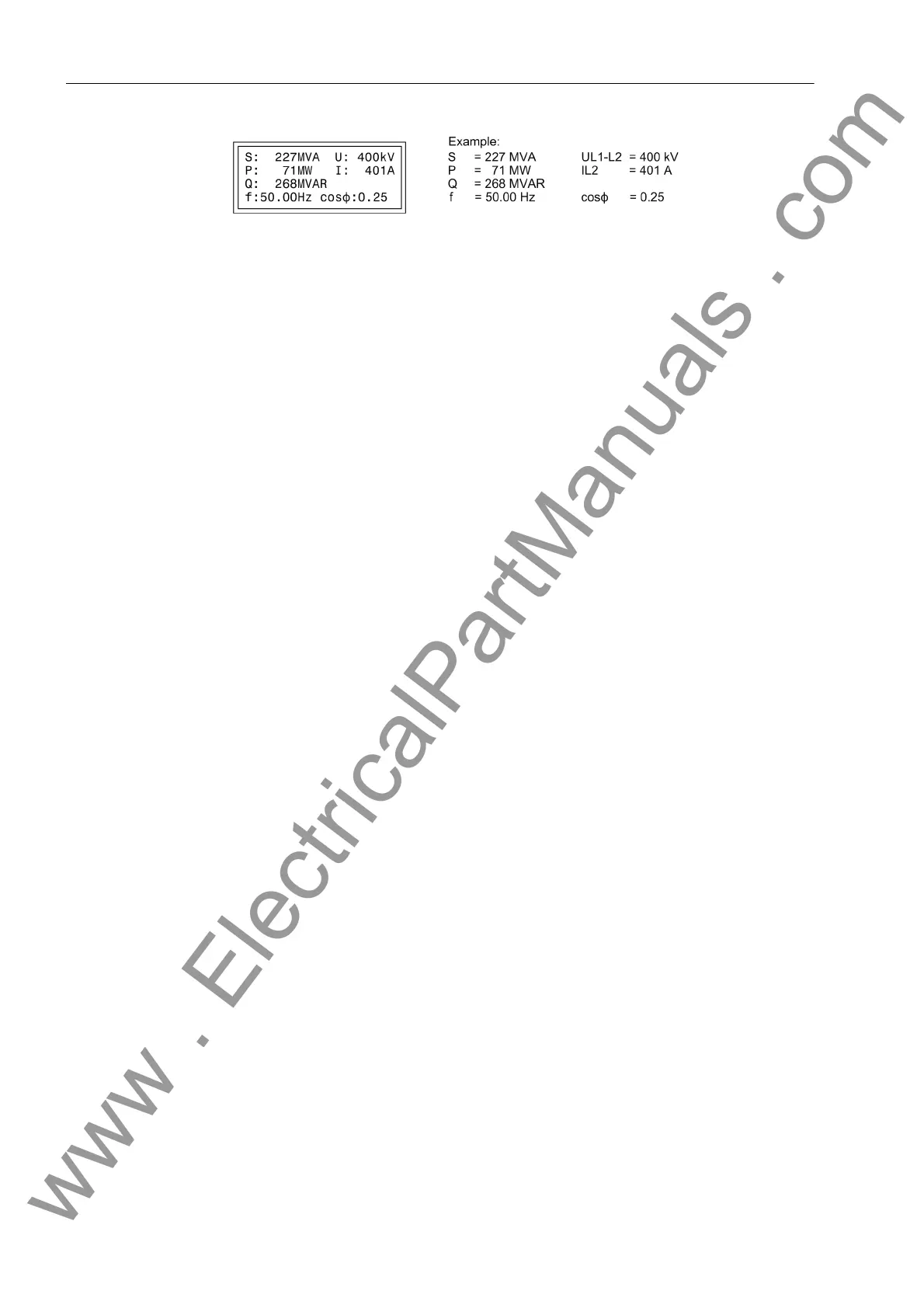
Figure 2-186 Operational measured values in the default display
Moreover, the device has several event buffers for operational annunciations, switch-
ing statistics, etc., which are saved against loss of auxiliary supply by means of a
backup battery. These indications can be displayed on the LCD at any time by selec-
tion using the keypad or transferred to a personal computer via the serial service or
operator interface. Readout of indications during operation is described in detail in the
SIPROTEC
®
4 System Description.
After a fault on the system, for example, important information about the progression
of the fault can be retrieved, such as the pickup of a protective element or the initiation
of a trip signal. The time the initial occurrence of the short-circuit fault occurred is ac-
curately provided via the system clock. The progress of the disturbance is output with
a relative time referred to the instant of fault detection, so that the duration of the fault
until tripping and up to reset of the trip command can be ascertained. The resolution
of the time information is 1 ms.
With a PC and the DIGSI
®
protection data processing software it is also possible to
retrieve and display the events with the convenience of visualization on a monitor and
a menu-guided dialog. The data may either be printed or stored for evaluation at a later
time and place.
Information to a
C o n t r o l C e n t r e
If the device has a serial system interface, stored information may additionally be
transferred via this interface to a centralized control and storage device. Several com-
munication protocols are available for the transfer of this information.
You may test whether the information is transmitted correctly with DIGSI
®
.
Also, the information transmitted to the control centre can be influenced during oper-
ation or tests. The IEC 60870-5-103 protocol allows to identify all messages and mea-
sured values transferred to the central control system with an added message „ test
operation“- bit while the device is being tested on site (test mode). This identification
prevents the messages from being incorrectly interpreted as resulting from an actual
power system disturbance or event. Alternatively, you may disable the transmission of
annunciations to the system interface during tests („transmission block“).
To influence information at the system interface during test mode („test mode“ and
„transmission block“), a CFC logic is required. Default settings already include this
logic (see Appendix).
The SIPROTEC
®
4 System Description describes in detail how to activate and deac-
tivate test mode and blocked data transmission.
www . ElectricalPartManuals . com
 Loading...


