2.24 Ancillary Functions
417
7SD5 Manual
C53000-G1176-C169-1
The latched conditions are protected against loss of the auxiliary voltage. They are
reset
• On site by pressing the LED key on the relay,
• Remotely using a binary input configured for that purpose,
• Using one of the serial interfaces,
• Automatically at the beginning of a new pickup.
Status messages should not be latched. Also, they cannot be reset until the condition
to be reported has been cancelled. This applies to, e.g. indications from monitoring
functions, or the like.
A green LED displays operational readiness of the relay („RUN“), and cannot be reset.
It goes out if the self-check feature of the microprocessor recognizes an abnormal oc-
currence, or if the auxiliary voltage fails.
When auxiliary voltage is present but the relay has an internal malfunction, the red
LED („ERROR“) lights up and the processor blocks the relay.
DIGSI
®
enables you to control selectively each output relay and LED of the device
and, in doing so, check the correct connection to the system. In a dialog box you can,
for instance, cause each output relay to pick up, and thus test the wiring between the
7SD5 and the station, without having to create the indications masked to it.
Information via
D i s p l a y P a n e l o r P C
Events and conditions can be read out on the display on the front panel of the relay.
Using the front operator interface or the rear service interface, for instance, a personal
computer can be connected, to which the information can be sent.
In the quiescent state, i.e. as long as no system fault is present, the LCD can display
selectable operational information (overview of the operational measured values) (de-
fault display). In the event of a system fault, information regarding the fault, the so-
called spontaneous displays, are displayed instead. After the fault indications have
been acknowledged, the quiescent data are shown again. Acknowledgement can be
performed by pressing the LED buttons on the front panel (see above).
Figure 2-185 shows the default display in a 4-line display as preset. The default
display can be configured in the graphic display. For more information see the SIPRO-
TEC
®
4 System Description and the Display Editor manual.
Various default displays can be selected via the arrow keys. Parameter 640 can be
set to change the default setting for the default display page shown in idle state. Two
examples of possible default display selections are given below.
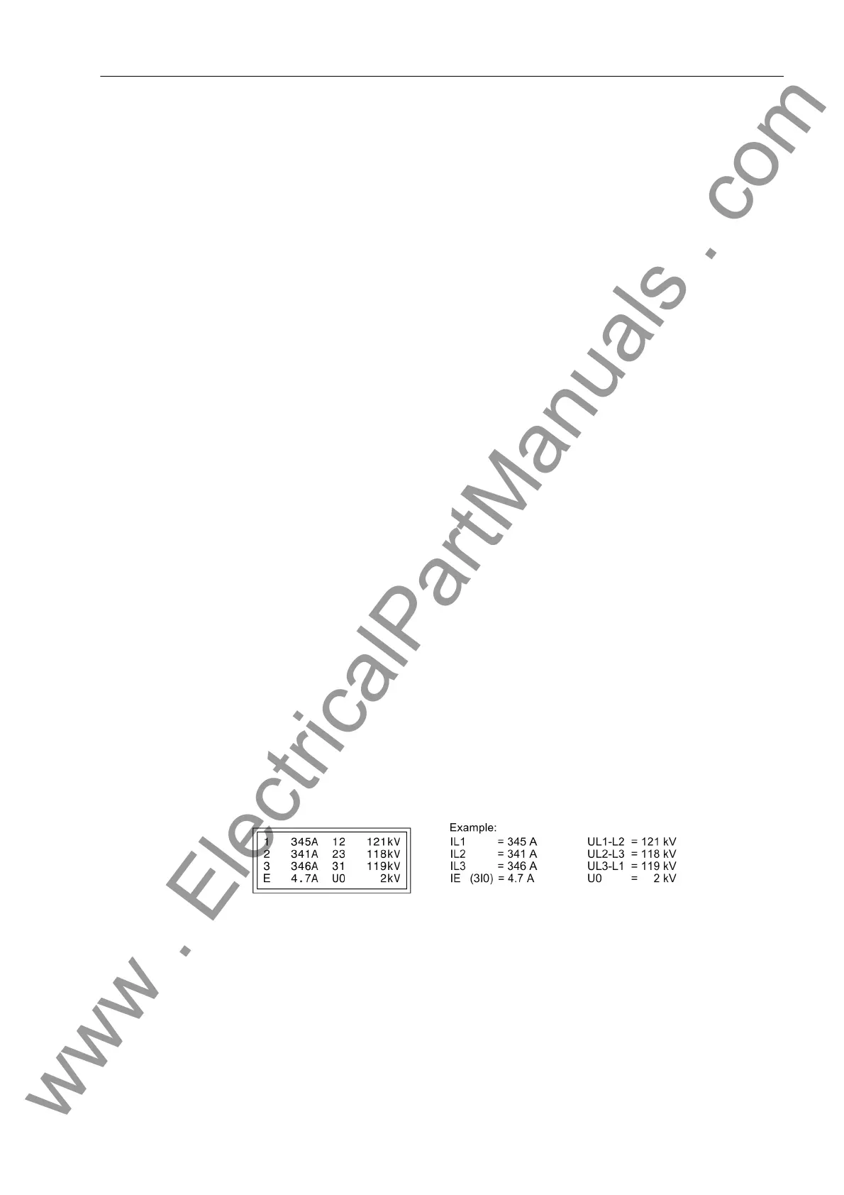
Figure 2-185 Operational measured values in the default display
Default display 3 shows the measured values U
L1-L2
and I
L2
.
www . ElectricalPartManuals . com
 Loading...


