3 Mounting and Commissioning
454
7SD5 Manual
C53000-G1176-C169-1
Work on the Plug
Connectors
Caution!
Mind electrostatic discharges:
Non–observance can result in minor personal injury or property damage.
When handling plug connectors, electrostatic discharges may emerge. These must be
avoided by previously touching an earthed metal surface.
Do not plug or unplug interface connectors under voltage!
The assembly of the boards for the housing size
1
/
2
is shown in Figure 3-3 and for the
housing size
1
/
1
in Figure 3-4.
• Disconnect the plug connector of the ribbon cable between the front cover and the
processor board C-CPU-1 (No. 1) at the front cover side. For this purpose push
apart the top and bottom latches at the plug connector so that the ribbon cable con-
nector is pressed out.
• Disconnect the ribbon cables between the processor board C-CPU-1 (No. 1 in
Figure 3-3 or 3-4) and the input/output board I/O (according to order variant No. 2
to No. 3 in Figure 3-3 or 3-4).
• Remove the boards and place them on a surface suitable for electrostatically sen-
sitive devices (ESD). In the case of the device variant for panel surface mounting,
please be aware of the fact a certain amount of force is required in order to remove
the C-CPU-1 module due to the existing plug connectors.
• Check the jumpers according to Figures 3-5 to 3-11 and the following information,
and as the case may be change or remove them.
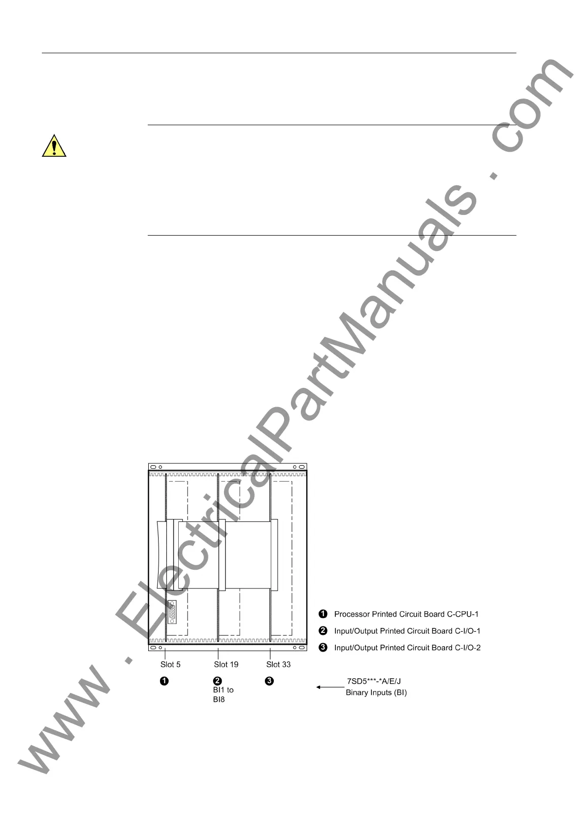
Figure 3-3 Front view with housing size
1
/
2
after removal of the front cover (simplified and
scaled down)
www . ElectricalPartManuals . com
 Loading...


