3 Mounting and Commissioning
456
7SD5 Manual
C53000-G1176-C169-1
Table 3-3 Jumper settings of the Life Contact on the input/output board C-I/O-1
Depending on the device version the contacts of some binary outputs can be changed
from normally open to normally closed (see Appendix, under Section A.2).
• In versions 7SD5***-*D/H/M (housing size
1
/
1
with 32 binary outputs) this is valid for
the binary outputs BO16 and BO24 (Figure 3-4, slot 19 left and right);
• In versions 7SD5***-*C/G/L (housing size
1
/
1
with 24 binary outputs) this is valid for
the binary output BO16 (Figure 3-4, slot 19 right);
• In versions 7SD5***-*P/R/T (housing size
1
/
1
with 32 binary outputs and command
acceleration) this is valid for the binary output BO24 (Figure 3-4, slot 19 left).
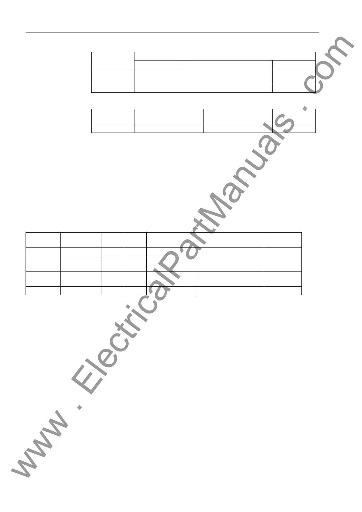
Table 3-4 shows the jumper settings for the contact mode.
Table 3-4 Jumper settings for contact mode of the binary outputs BO16 and BO24 on the input/output board C–I/O-1
Interchangeable Cannot be
changed
Fuse T2H250V T4H250V
Jumper
Open in Quiescent State
(NO)
Closed in Quiescent State
(NC)
Factory Setting
X40 1-2 2-3 2-3
Jumper
Nominal Voltage
60/110/125 VDC 110/125/220/250 VDC 115 VAC 24/48 VDC
Device
7SD5***–*
Printed Circuit
Board
For Jumper Open in Quies-
cent State (NO)
Closed in Quiescent State
(NC)
Factory
Setting
D/H/M Slot 19 left side BO 16 X40 1-2 2-3 1-2
Slot 19 right
side
BO 24 X40 1-2 2-3 1-2
C/G/L Slot 19 right
side
BO 16 X40 1-2 2-3 1-2
P/R/T Slot 19 left side BO 24 X40 1-2 2-3 1-2
www . ElectricalPartManuals . com
 Loading...


