3 Mounting and Commissioning
464
7SD5 Manual
C53000-G1176-C169-1
With jumper X11 the flow control which is important for modem communication.
Table 3-11 Jumper setting for CTS (Clear To Send, flow control) on the interface module
1)
Default Setting
Jumper Setting 2-3: The connection to the modem is usually carried out with a star
coupler or fibre-optic converter. Therefore the modem control signals according to
RS232 standard DIN 66020 are not available. Modem signals are not required since
communication to SIPROTEC
®
4 devices is always carried out in the half duplex
mode. Please use the connection cable with order number 7XV5100-4.
Jumper Setting 1-2: This setting makes the modem signals available, i. e. for a direct
RS232-connection between the SIPROTEC
®
4 device and the modem this setting can
be selected optionally. We recommend to use a standard RS232 modem connection
cable (converter 9-pin to 25-pin).
Note
For a direct connection to DIGSI
®
with Interface RS232, jumper X11 must be plugged
in position 2-3.
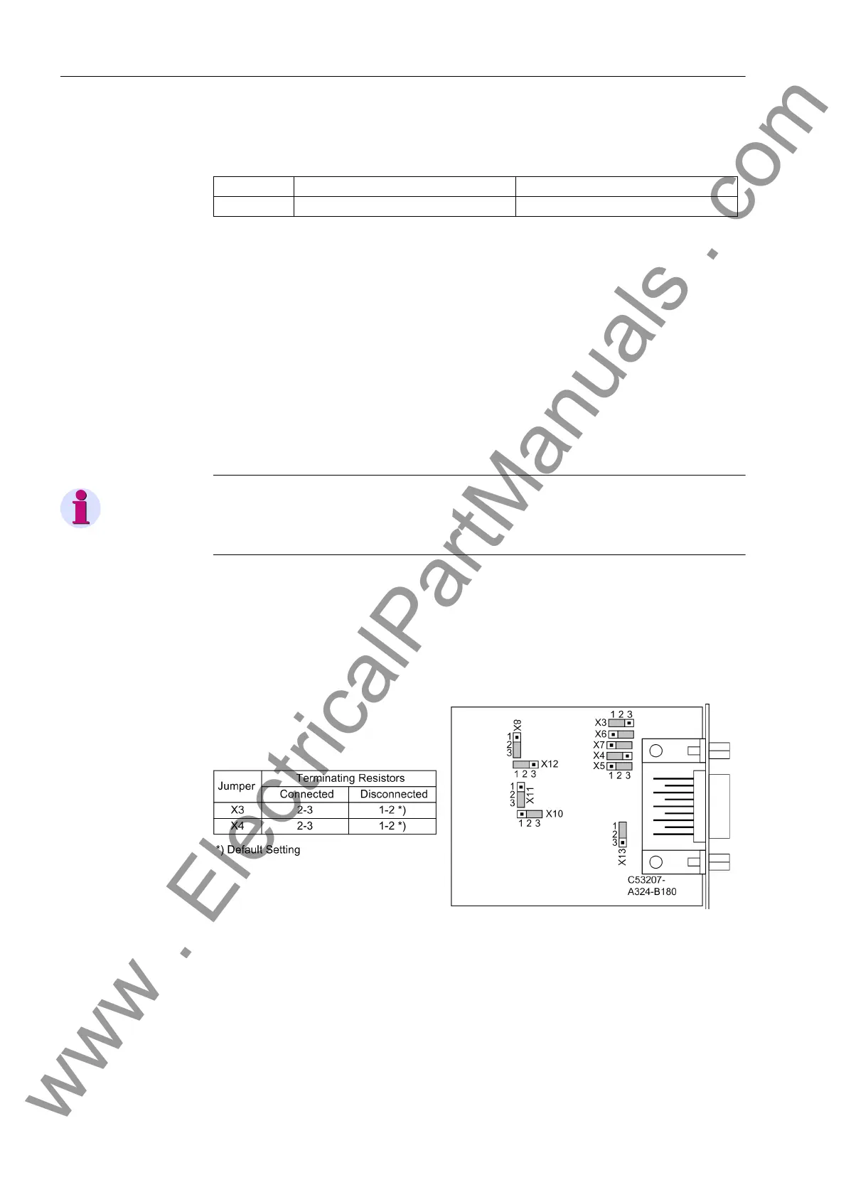
RS485 I n terface The following figure shows the location of the jumpers of interface RS485 on the inter-
face module.
Interface RS485 can be modified to interface RS232 and vice versa, according to
Figure 3-9.
Figure 3-10 Position of terminating resistors and the plug-in jumpers for configuration of the
RS485 interface
Jumper /CTS from Interface RS232 /CTS controlled by /RTS
X11 1-2 2-3
1)
www . ElectricalPartManuals . com
 Loading...


