2.1 General
47
7SD5 Manual
C53000-G1176-C169-1
Voltage
Connection
The device contains four voltage measuring inputs, three of which are connected to
the set of voltage transformers. Various possibilities exist for the fourth voltage input
U
4
:
• Connection of the U
4
input to the open delta winding e-n of the voltage transformer
set:
Address 210 is then set to: U4 transformer = Udelta transf..
When connected to the e-n winding of a set of voltage transformers, the voltage
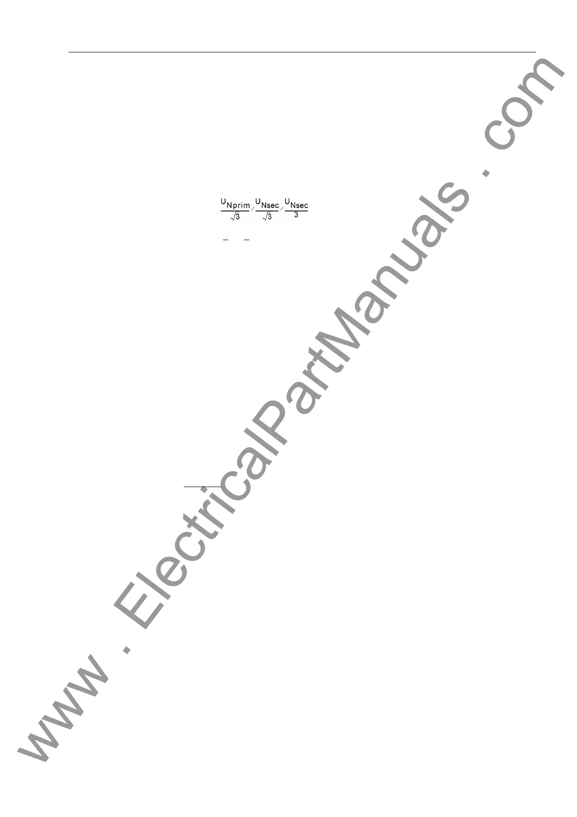
transformation ratio of the voltage transformers is usually:
The factor Uph/Udelta (secondary voltage, address 211 Uph / Udelta) must be
set to 3/√3
= √3 ≈ 1.73. For other transformation ratios, i.e. the formation of the dis-
placement voltage via an interconnected transformer set, the factor must be cor-
rected accordingly. This factor is of importance if the 3U
0
> protective element is
used and for the monitoring of the measured values and the scaling of the measure-
ment and disturbance recording signals.
• Connection of the U
4
input to the busbar voltage in order to perform the synchro-
nism check:
Address 210 is then set to: U4 transformer = Usync transf..
If the transformation ratio differs from that of the line voltage transformers this can
be adapted with the setting in address 215 U-line / Usync. In address 212
Usync connect., the type of voltage used by the busbar for synchronism check
is configured. The device then selects automatically the appropriate feeder voltage.
If the two measuring points used for synchronism check — i.e. feeder voltage trans-
former and busbar voltage transformer — are not separated by devices that cause
a relative phase shift, then the parameter in address 214 ϕ Usync-Uline is not
required. This parameter can only be altered with DIGSI
®
under Additional Set-
tings. If however a power transformer is switched in between, its vector group must
be adapted. The phase angle from U
Line
to U
Bus
is evaluated positively.
Example
: (see also Figure 2-3)
Busbar 400 kV primary, 110 V secondary,
Feeder 220 kV primary, 100 V secondary,
Transformer 400 kV / 220 kV, vector group Dy(n) 5
The transformer vector group is defined from the high side to the low side. In this
example, the feeder voltage is connected to the low voltage side of the transformer.
If Usync (busbar or high voltage side) is placed at zero degrees, then Uline is at 5
x 30° (according to the vector group) in the clockwise direction, i.e. at –150°. A pos-
itive angle is obtained by adding 360°:
Address 214: ϕ Usync-Uline = 360° - 150° = 210°.
The busbar transformers supply 110 V secondary for primary operation at nominal
value while the feeder transformer supplies 100 V secondary. Therefore, this differ-
ence must be balanced:
Address 215: U-line / Usync = 100 V / 110 V = 0.91.
www . ElectricalPartManuals . com
 Loading...


