2 Functions
48
7SD5 Manual
C53000-G1176-C169-1
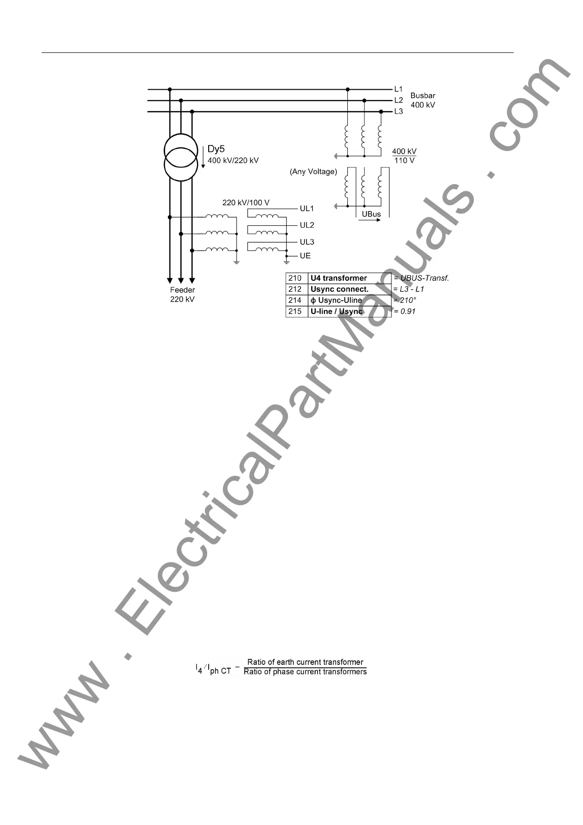
Figure 2-3 Busbar voltage measured via transformer
• Connection of the U
4
input to any other voltage signal U
X
, which can be processed
by the overvoltage protection function:
Address 210 is then set to: U4 transformer = Ux transformer.
• If the input U
4
is not required, set:
Address 210 U4 transformer = Not connected.
Also in this case the factor Uph / Udelta (address 211, see above) is of impor-
tance, as it is utilised for the scaling of the measurement and disturbance recording
data.
Current Connection The device features four current measurement inputs, three of which are connected
to the set of current transformers. Various possibilities exist for the fourth current input
I
4
:
• Connection of the I
4
input to the earth current in the starpoint of the set of current
transformers on the protected feeder (normal connection):
Address 220 is then set to: I4 transformer = In prot. line and address
221 I4/Iph CT = 1.
• Connection of the I
4
input to a separate earth current transformer on the protected
feeder (e.g. a summation CT or core balance CT):
Address 220 is then set to: I4 transformer = In prot. line and address
221 I4/Iph CT is set:
This is independent of whether the device has a normal measuring current input for
I
4
or a sensitive measuring current input (if necessary with I
E
transformer for earth
fault protection).
www . ElectricalPartManuals . com
 Loading...


