3.3 Commissioning
499
7SD5 Manual
C53000-G1176-C169-1
the feeder in the direction of the busbar rotates the voltage. An example is shown in
Section 2.1.2.1.
If necessary, different transformation ratios of the transformers on the busbar and the
feeder may have to be considered under address 215 U-line / Usync.
The synchronism and voltage check must be switched ON under address 3501 FCT
Synchronism .
An additional help for the connection control are the messages 2947 „Sync.
Udiff>“ and 2949 „Sync. ϕ-diff>“ in the spontaneous annunciations.
• Circuit breaker is open. The feeder is isolated (zero voltage). The VTmcb's of both
voltage transformer circuits must be closed.
• For the synchronism check the program OVERRIDE = YES (address 3519) is set;
the other programs (addresses 3515 to 3518) are set to NO.
• Via binary input (No. 2906 „>Sync. Start AR“) initiate the measuring request.
The synchronism check must release closing (message „Sync. release“, FNo.
2951). If not, check all relevant parameters again (synchrocheck configured and
enabled correctly, see Sections 2.1.1.3, 2.1.2.1 and 2.16.2).
• Set address 3519 OVERRIDE to NO.
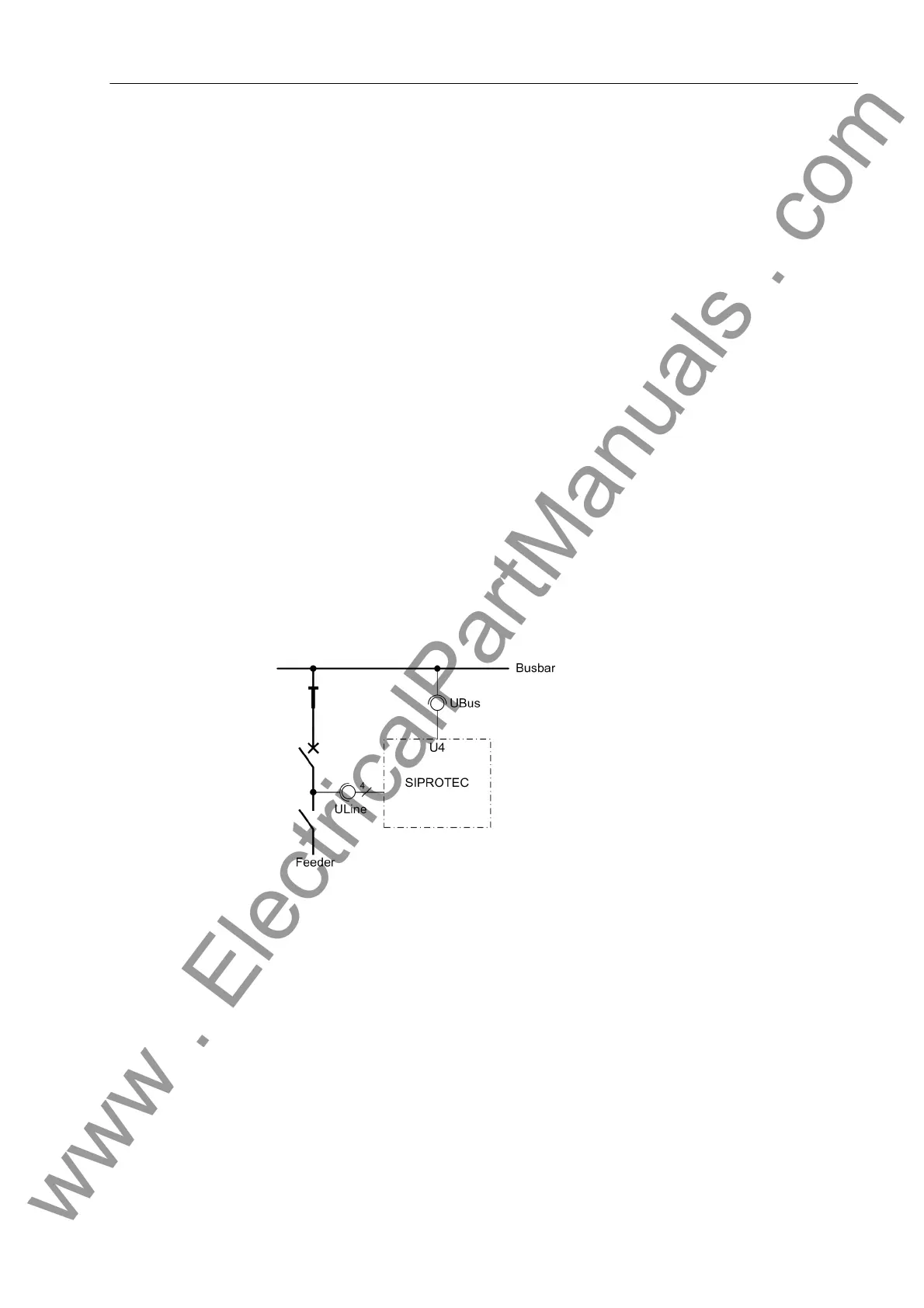
• Then the circuit breaker is closed while the line isolator is open (see Figure 3-29).
Both voltage transformers therefore measure the same voltage.
• The program SYNC-CHECK = YES (address 3515) is set for synchronism check.
• Via binary input (No. 2906 „>Sync. Start AR“) initiate the measuring request.
The synchronism check must release closing (message „Sync. release“, FNo.
2951).
Figure 3-29 Measuring voltages for the synchronism check
www . ElectricalPartManuals . com
 Loading...


