2.1 General
53
7SD5 Manual
C53000-G1176-C169-1
According to the above table, address 251 should be set to 1.50 if the calculated ratio
is higher than 1.50. This leads to the following setting values:
Address 251 K_ALF/K_ALF_N = 1.50
Address 253 E% ALF/ALF_N = 3.0
Address 254 E% K_ALF_N = 10.0
The presettings correspond to current transformers 10P with nominal burden
Of course, only those settings are reasonable where address 253 E% ALF/ALF_N is
set lower than address 254 E% K_ALF_N.
Power Transformer
with Voltage Regu-
lation
If the protected object covers a power transformer with voltage regulation, a differential
current may occur even during normal healthy operation under steady-state condi-
tions. This differential current depends on the current intensity as well as on the posi-
tion of the tap changer of the transformer. Since this differential current is current-pro-
portional it is meaningful to consider it like a current transformer error. You may
calculate the maximum differential current at the limits of the tap changer under
nominal conditions (referred to the mean current) and add it to the current transformer
error as discussed above (addresses 253 and 254). This correction is performed only
at that relay facing the regulated winding of the power transformer.
Calculation example:
Transformer YNd5
35 MV
110 kV/25 kV
Y–winding with tap changer ±10 %
From this resulting:
Nominal current at nominal voltage I
N
= 184 A
Nominal current at U
N
+ 10 % I
min
= 167 A
Nominal current at U
N
– 10 % I
max
= 202 A
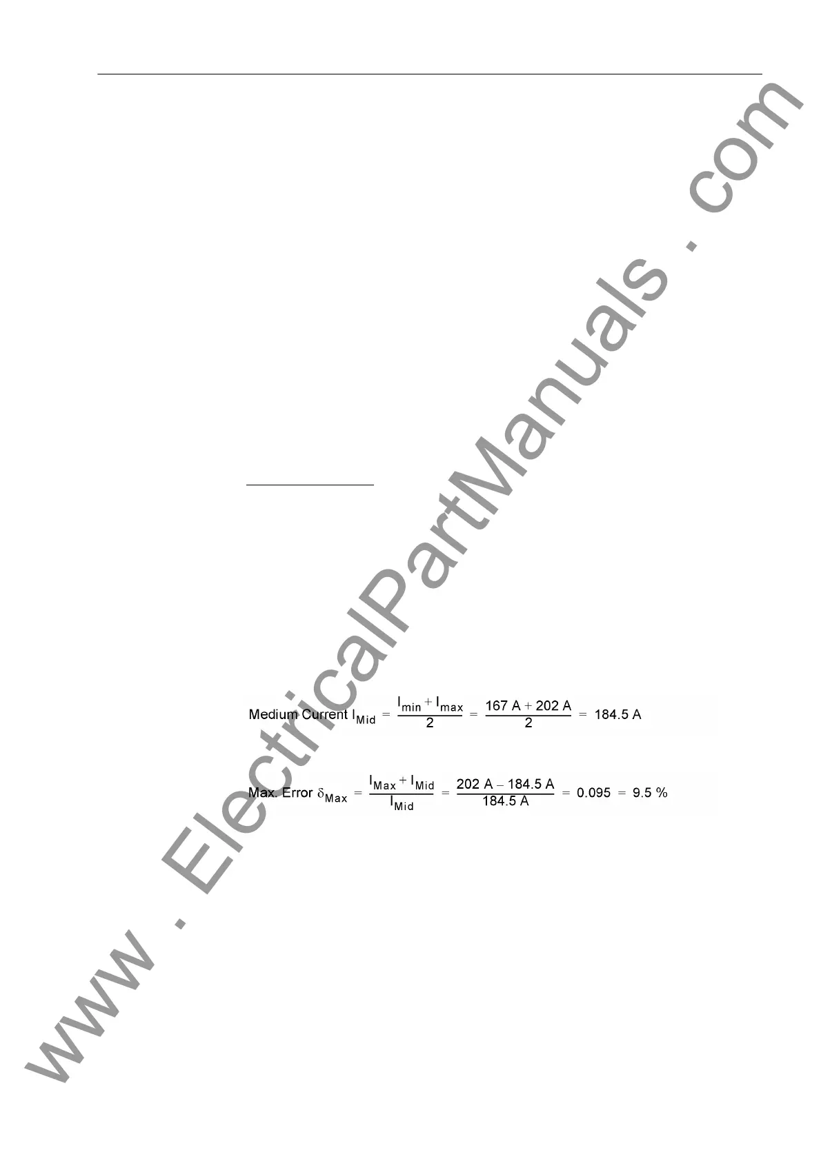
The maximum deviation from this mean current is
This maximum deviation δ
max
[in %] has to be added to the current transformer errors
as determined above, addresses 253 E% ALF/ALF_N and 254 E% K_ALF_N.
It must be considered that this deviation is referred to the mean current value between
the extrema of the tap changer position at nominal apparent power, not to the current
value at nominal voltage and nominal power. This demands a further correction of the
data of the protected object as discussed in Section 2.1.4 under margin heading „To-
pological Data for Transformers (optional)“.
www . ElectricalPartManuals . com
 Loading...


