2 Functions
52
7SD5 Manual
C53000-G1176-C169-1
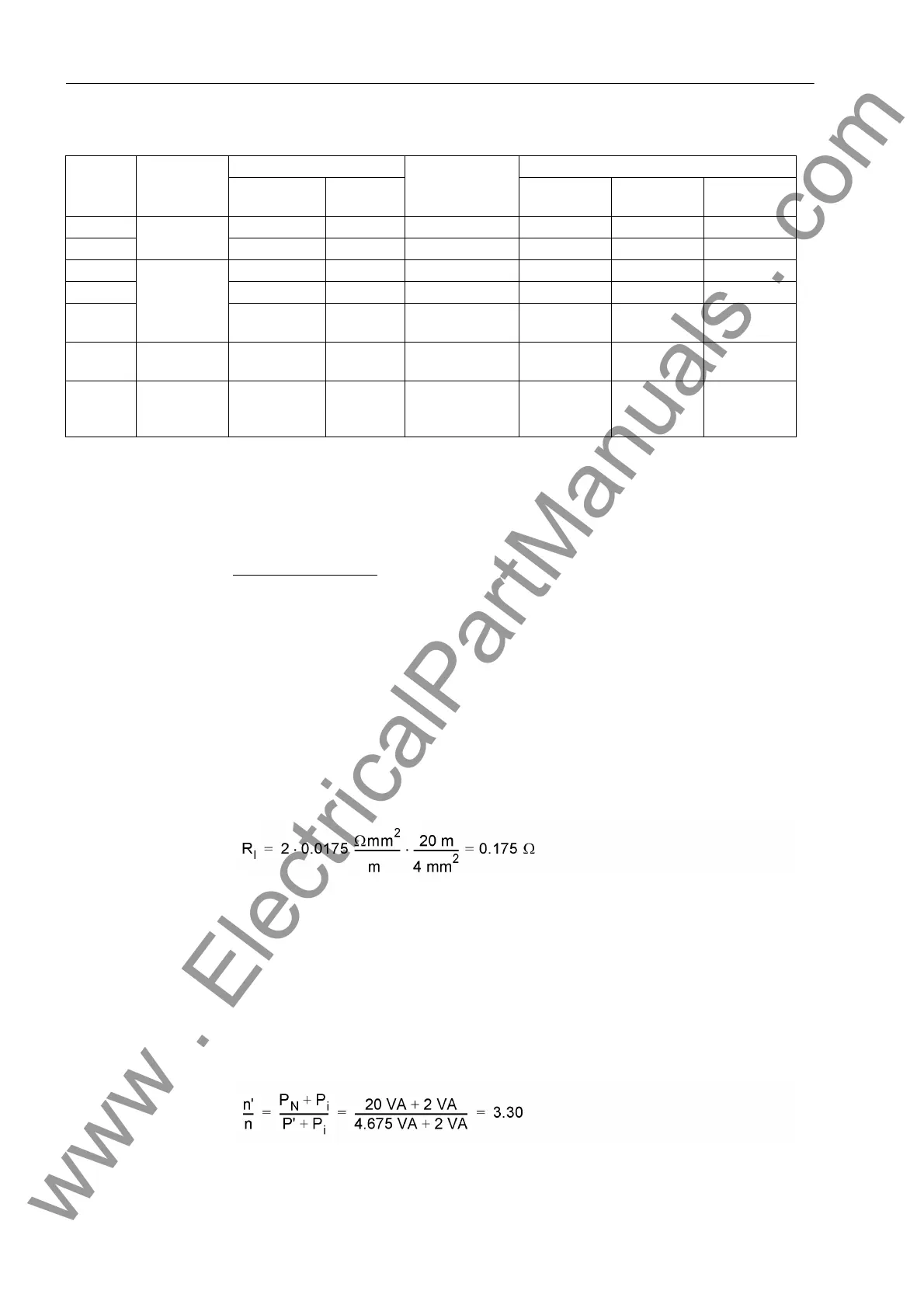
Table 2-1 Recommended settings for current transformer data
1)
If n'/n ≤ 1.50, setting = calculated ratio; if n'/n > 1.50, setting = 1.50
With this data the device establishes an approximate CT error characteristic and cal-
culates the restraint quantity (see also Section 2.3).
Calculation example:
Current transformers 5P10; 20 VA
Transformation 600 A / 5 A
Internal burden 2 VA
Secondary lines 4 mm
2
CC
Length 20 m
Device 7SD5 , I
N
= 5 A
Burden at 5 A, 0.3 VA
The resistance of secondary lines is (with the resistivity for copper ρ
Cu
= 0.0175
Ωmm
2
/m)
Here, the most unfavourable case is assumed, i.e. the current (as it is the case with
single-phase faults) flows back and forth via the secondary lines (factor 2). From that
the power for nominal current I
N
= 5 A is calculated
P
l
= 0.175 Ω · (5 A)
2
= 4.375 VA
The entire connected burden consists of the burden of the incoming lines and the
burden of the device:
P' = 4.375 VA + 0.3 VA = 4.675 VA
Thus the ratio of the accuracy limit factors is as follows
CT Class Standard Error at Rated Current Error at Rated
Accuracy Limit
Factor
Recommended Settings
Transforma-
tion Ratio
Angle Address 251 Address 253 Address 254
5P IEC 60044-1 1.0 % ± 60 min ≤ 5% ≤ 1.50
1)
3.0 % 10.0 %
10P 3.0 % — ≤ 10 % ≤ 1.50
1)
5.0 % 15.0 %
TPX IEC 60044-1 0.5 % ± 30 min ε ≤ 10 % ≤ 1.50
1)
1.0 % 15.0 %
TPY 1.0 % ± 30 min ε ≤ 10 % ≤ 1.50
1)
3.0 % 15.0 %
TPZ 1.0 % ± 180 min
± 18 min
ε ≤ 10 %
(only I∼)
≤ 1.50
1)
6.0 % 20.0 %
PX IEC 60044-1
BS: Class X
≤ 1.50
1)
3.0 % 10.0 %
C100
to
C800
ANSI ≤ 1.50
1)
5.0 % 15.0 %
www . ElectricalPartManuals . com
 Loading...


