4.5 Distance Protection (optional)
537
7SD5 Manual
C53000-G1176-C169-1
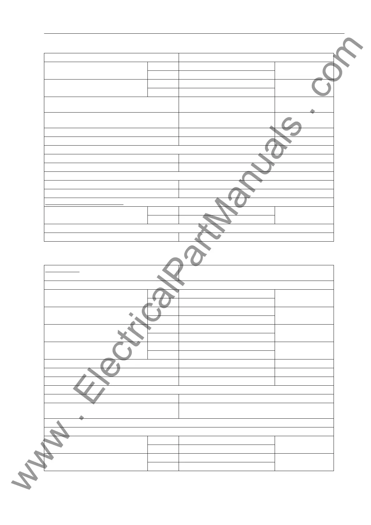
Distance Measurement
Characteristic Different stages with settable inclinations
Minimum current Iph> for I
N
= 1 A 0.10 A to 4.00 A Increments 0.01 A
for I
N
= 5 A 0.50 A to 20.00 A
Current in fault angle range Iϕ for I
N
= 1 A 0.10 A to 8.00 A Increments 0.01 A
for I
N
= 5 A 0.50 A to 40.00 A
Undervoltage phase-earth Uphe
(segregated for Iph>, Iϕ> and Iph>>)
20 V to 70 V Increments 1 V
Undervoltage phase-phase Uphph
(segregated for Iph>, Iϕ> and Iph>>)
40 V to 130 V Increments 1 V
Lower threshold angle ϕ>30° to 60° In increments of 1°
Upper threshold angle ϕ<90° to 120° In increments of 1°
Dropout to pickup ratio
Iph>, Iϕ> Approx. 0.95
Uphe, Uphph Approx. 1.05
Measuring tolerances for sinusoidal measured values
Values of U, I ± 5%
Angle ϕ± 3°
Impedance starting (selectable)
Minimum current Iph> for I
N
= 1 A 0.05 A to 4.00 A Increments 0.01 A
for I
N
= 5 A 0.25 A to 20.00 A
The thresholds of the polygon set to the highest level are relevant taking into consideration the corresponding direction
Dropout/pickup ratio Approx. 1.05
Characteristic Polygonal or MHO characteristic (depending on ordered vari-
ant); 5 independent zones and 1 controlled zone
Setting ranges of polygon:
I
Ph
> = min. current, phases for I
N
= 1 A 0.05 A to 4.00 A Increments 0.01 A
for I
N
= 5 A 0.25 A to 20.00 A
X = reactance reach for I
N
= 1 A 0.050 Ω to 600,000 Ω Increments 0.001 Ω
for I
N
= 5 A 0.010 Ω to 120,000 Ω
R = resistance tolerance phase-phase for I
N
= 1 A 0.050 Ω to 600,000 Ω Increments 0.001 Ω
for I
N
= 5 A 0.010 Ω to 120,000 Ω
RE = resistance tolerance phase-earth for I
N
= 1 A 0.050 Ω to 600,000 Ω Increments 0.001 Ω
for I
N
= 5 A 0.010 Ω to 120,000 Ω
ϕ
Line
= line angle 30° to 89° Increments 1°
ϕ
Dist
= angle of distance protection characteristic 30° to 90° Increments 1°
α
Pol
= tilt angle for 1st zone 0° to 30° Increments 1°
Direction determination for polygonal characteristic:
For all types of faults With phase-true, memorized or cross-polarized voltages
Directional sensitivity Dynamically unlimited
Stationary approx. 1V
Each zone can be set to operate in forward or reverse direction, non-directional or ineffective.
Setting ranges of the MHO characteristic:
I
Ph
> = min. current, phases for I
N
= 1 A 0.05 A to 4.00 A Increments 0.01 A
for I
N
= 5 A 0.25 A to 20.00 A
Z
r
= impedance reach for I
N
= 1 A 0.050 Ω to 200,000 Ω Increments 0.001 Ω
for I
N
= 5 A 0.010 Ω to 40,000 Ω
www . ElectricalPartManuals . com
 Loading...


