4 Technical Data
538
7SD5 Manual
C53000-G1176-C169-1
Times
Emergency Operation
ϕ
Line
= line angle 30° to 89° Increments 1°
ϕ
Dist
= angle of distance protection characteristic 30° to 90° Increments 1°
Polarization With memorized or cross-polarized voltages
Each zone can be set to operate in forward or reverse direction or ineffective.
Load trapezoid:
R
Load
= minimum load resistance for I
N
= 1 A 0.050 Ω to 600,000 Ω; ∞ Increments 0.001 Ω
for I
N
= 5 A 0.010 Ω to 120,000 Ω; ∞
ϕ
Load
= maximum load angle 20° to 60° Increments 1°
Dropout ratio
– Currents Approx. 0.95
– Impedances Approx. 1.06
Measured value correction Mutual impedance matching for parallel lines (order option)
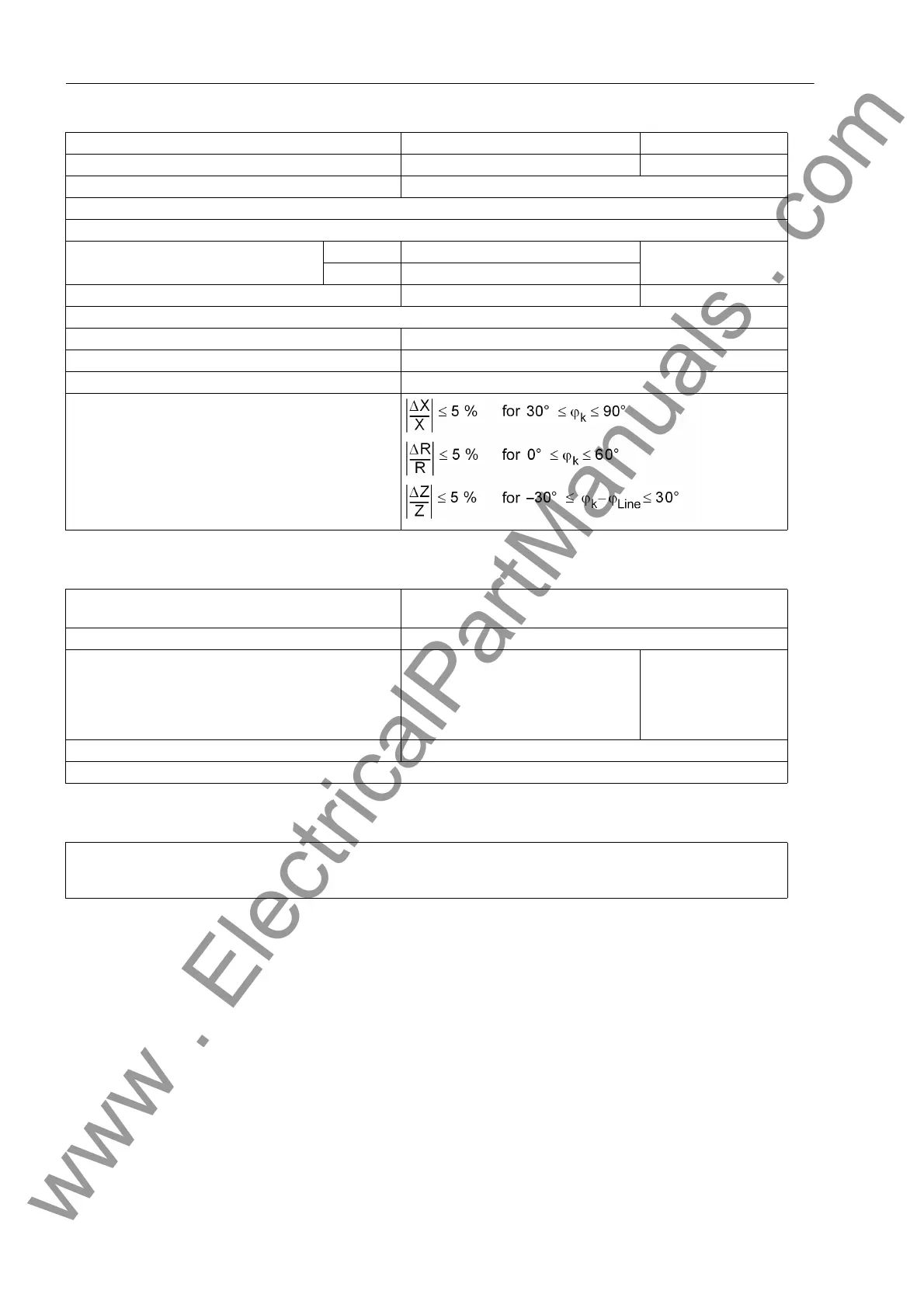
Measuring tolerances for sinusoidal measured values
Shortest trip time approx. 17 ms (50 Hz) / 15 ms (60 Hz) with fast relay and
approx. 12 ms (50 Hz) /10 ms (60 Hz) with high-speed relay
Dropout time Approx. 30 ms
Stage timers 0.00 s to 30.00 s; ∞
for all zones; separate time setting
possibilities for single-phase and
multi-phase faults for the zones Z1,
Z2, and Z1B
Increments 0.01 s
Time expiry tolerances 1 % of setting value or 10 ms
The set time is a pure delay time.
If the differential protection and the distance protection operate in parallel in the protective relay, emergency operation
will not be activated unless both protection functions have become ineffective.
In case of measured voltage failure, e.g. voltage transformer mcb trip see Section 4.14 „Time Overcurrent Protection“
www . ElectricalPartManuals . com
 Loading...


