2 Functions
86
7SD5 Manual
C53000-G1176-C169-1
For a protected object with more than two ends (and corresponding number of devic-
es), the further devices are assigned to their device IDs with the parameter addresses
4703 ID OF RELAY 3, 4704 ID OF RELAY 4, 4705 ID OF RELAY 5 and 4706
ID OF RELAY 6. A maximum of 6 ends with 6 devices is possible for a protected
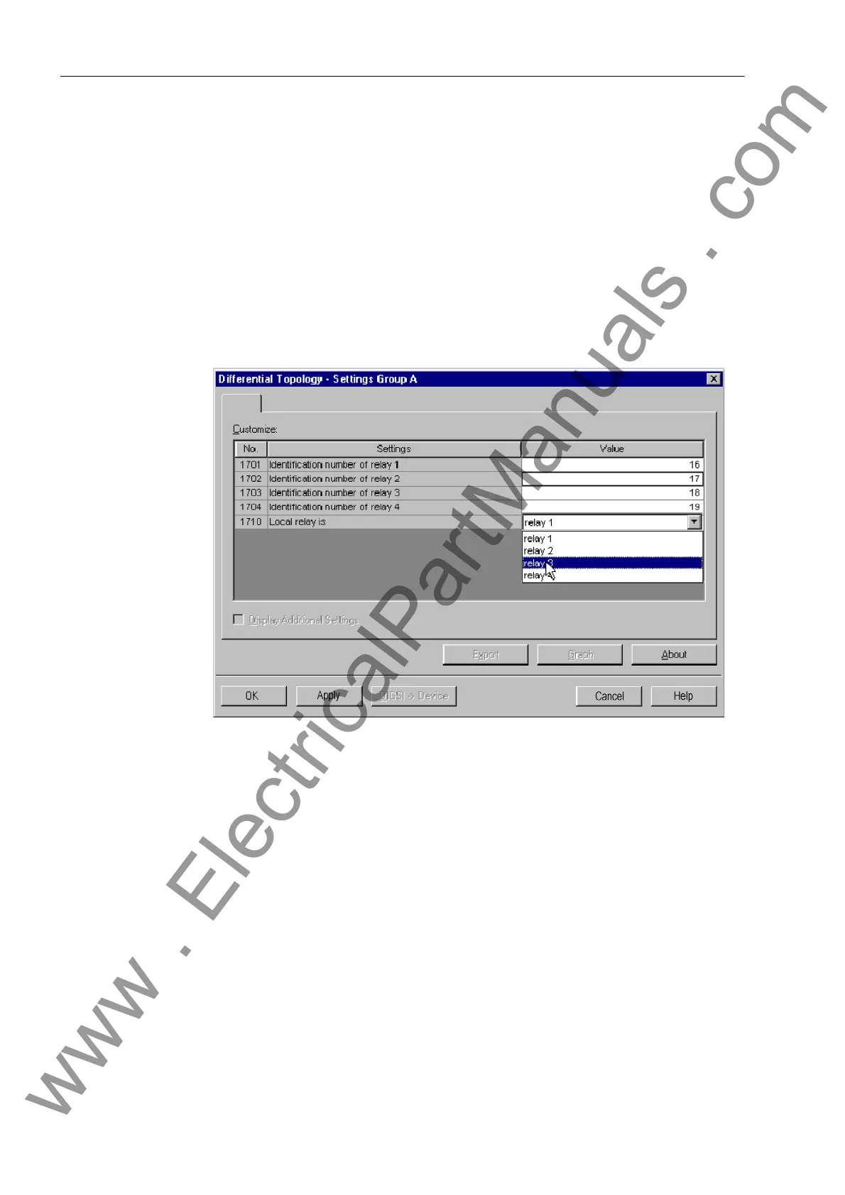
object. Figure 2-13 shows an example with 4 relays. During the configuration of the
protection functions (Section 2.1.1.3) the number of devices required for the relevant
case of application was set in address 147 NUMBER OF RELAY. Device IDs can be
entered for as many devices as were configured under that address, no further IDs are
offered during setting.
In address 4710 LOCAL RELAY you indicate the actual local device. Enter the index
for each device (according to the consecutive numbering used). Each index from 1 to
the entire number of devices must be used once, but may not be used twice.
Figure 2-13 Differential protection topology for 4 ends with 4 devices — example
Make sure that the parameters of the differential protection topology for the differential
protection system are conclusive:
• Each device index can only be used once.
• Each device index must be assigned unambiguously to one device ID.
• Each device index must be the index of a local device once.
• The device with index 1 is the source for the absolute time management (timing
master).
• The number of devices must be equal at all devices.
During startup of the protection system, the above listed conditions are checked. If one
out of these conditions is still not fulfilled, no differential protection operation is possi-
ble.
www . ElectricalPartManuals . com
 Loading...


