2 Functions
94
7SD5 Manual
C53000-G1176-C169-1
transformers on the line side is switched onto a fault. Since the frequency is not yet
known at this point of time, an increased restraint will be active until the actual frequen-
cy is determined. This may delay the tripping somewhat, but only close to the pickup
threshold, i.e. in case of very low-current faults.
These self-restraining quantities are calculated by each device from the total sum of
the possible deviations and transmitted to the other devices. In the same way as the
total currents (differential currents) are calculated (see above, „Transmission of Mea-
sured Values“), each device calculates thus the total sum of the restraining quantities
and thereby stabilize the differential currents.
It is due to the self-restraint that the differential protection works with a maximum of
sensitivity at all times, since the restraining quantities adapt themselves automatically
in a dynamic way to possible errors. In this way, even high-resistance faults, with high
load currents at the same time, can be detected effectively. Using GPS synchroniza-
tion, the self-restraining when using communication networks is minimize once more
since differences in the transmission times are compensated automatically. A maximal
sensitivity of the differential protection consists of an optical-fibre connection.
I n ru s h R e st rai nt If the protected area includes a power transformer, a high inrush current can be ex-
pected when connecting the transformer. This inrush current flows into the protected
zone but does not leave it again.
The inrush current can amount to a multiple of the nominal current and is character-
ised by a considerable 2nd harmonic content (double nominal frequency) which is
practically absent during a short-circuit. If the second harmonic content in the differen-
tial current exceeds a selectable threshold, tripping is blocked.
The inrush restraint has an upper limit: if a certain (adjustable) current value is exceed-
ed, it will not be effective any more, since there must be an internal current-intensive
short-circuit.
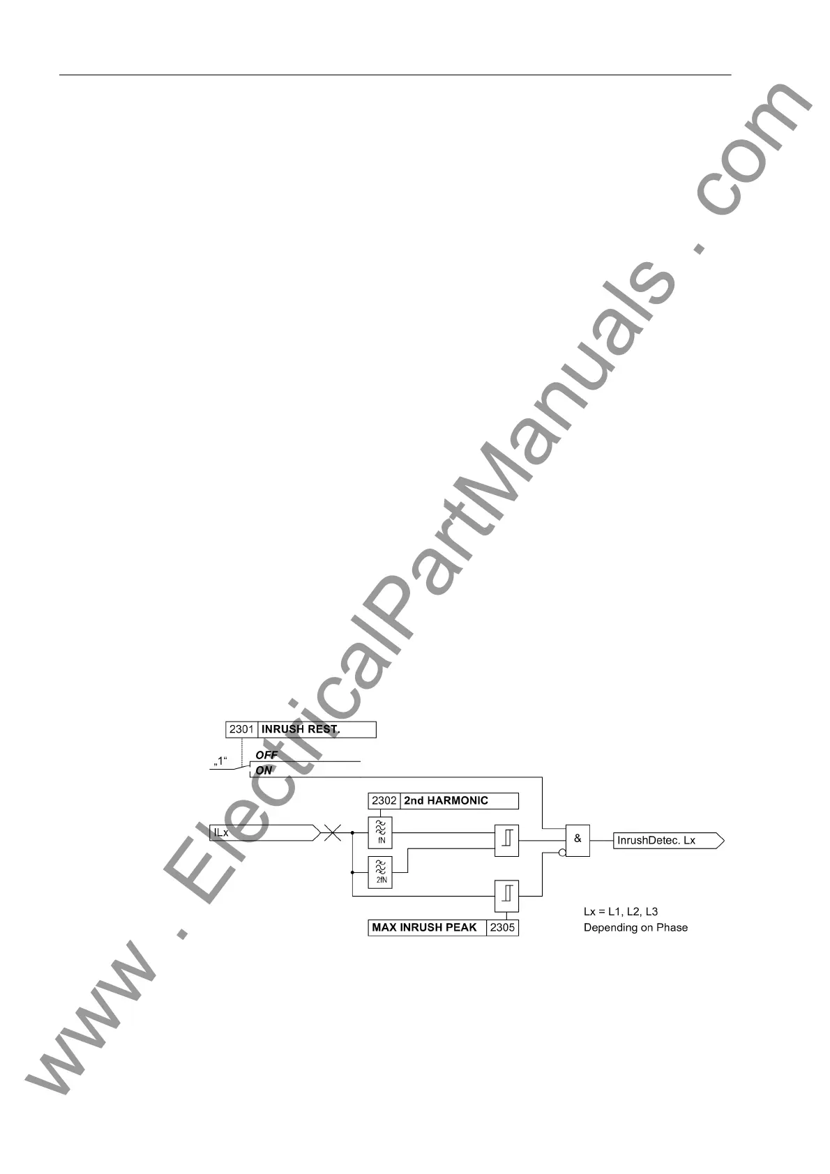
Figure 2-20 shows a simplified logic diagram. The conditions for the inrush restraint
are examined in each device in which this function has been activated. The blocking
condition is transmitted to all devices so that it is effective at all ends of the protected
object.
Figure 2-20 Logic diagram of the inrush restraint for one phase
Since inrush stabilization operates individually for each phase, the protection is fully
operative even when the transformer is switched onto a single-phase fault, whereby
an inrush current may possibly flow through one of the undisturbed phases. It is, how-
www . ElectricalPartManuals . com
 Loading...


