3.1 Mounting and Connections
243
7UM61 Manual
C53000-G1176-C127-3
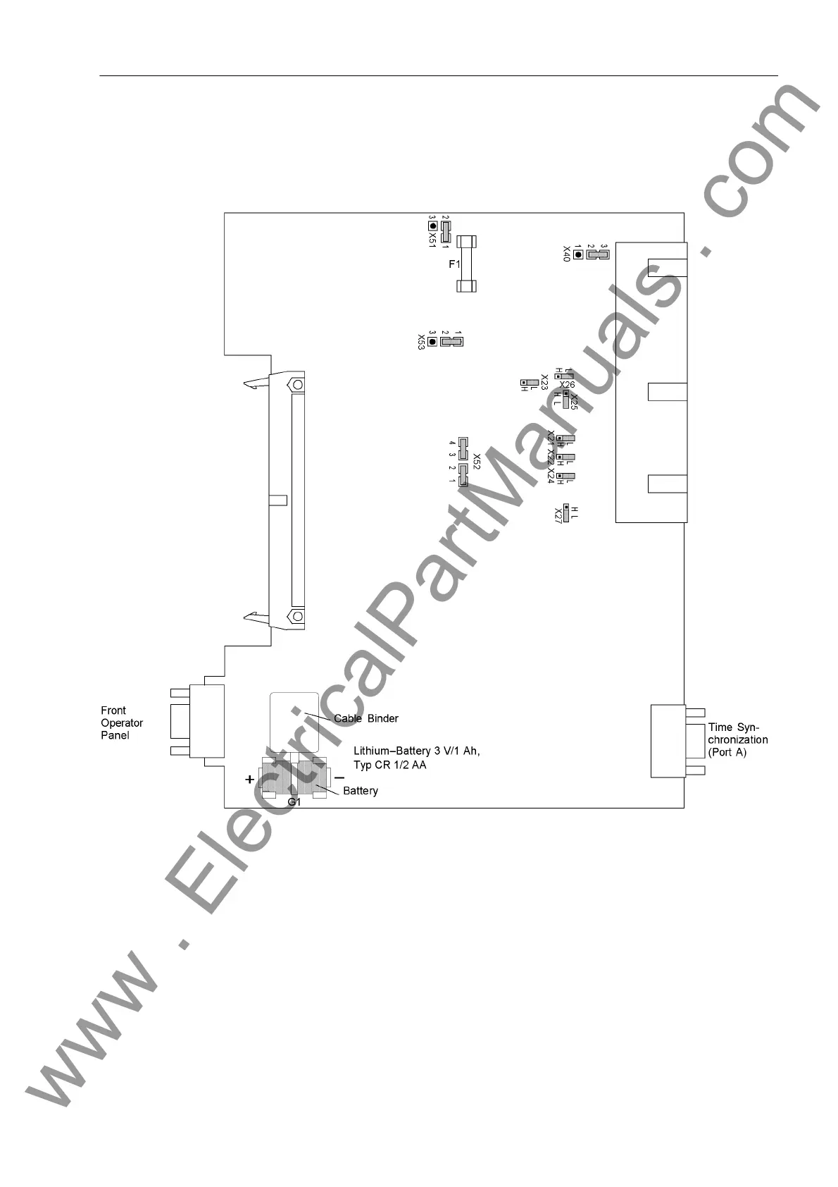
Processor board
B–CPU for
7UM61.../CC
The following figure depicts the PCB layout for devices from version 7UM61.../CC.
The location of the miniature fuse (F1) and of the buffer battery (G1) are shown in the
following figure.
Figure 3-4 B–CPU processor PCB for devices from version.../CC with jumper settings required for checking configu-
ration settings
For devices from version 7UM61.../CC, the jumpers for the set nominal voltage of the
integrated power supply are checked in accordance with Table 3-4, the quiescent state
of the life contact in accordance with Table 3-5 and the selected control voltages of
binary inputs BI1 through BI7 accordance with Table 3-6.
www . ElectricalPartManuals . com
 Loading...


