3.1 Mounting and Connections
241
7UM61 Manual
C53000-G1176-C127-3
3.1.2.3 Switch Elements on the PCBs
Processor board
B–CPU for
7UM61.../BB
There are two different releases of the B–CPU board a different layout and setting of
the jumpers. The following figure depicts the layout of the PCB for processor board
version up to 7UM61.../BB.
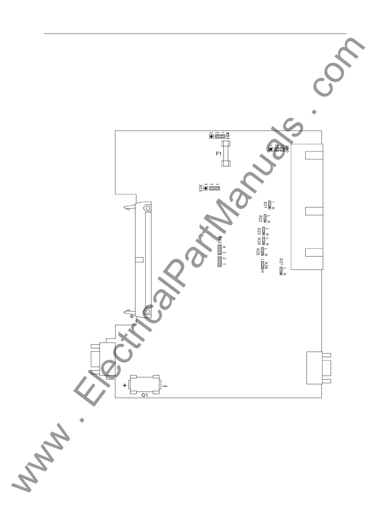
The location and ratings of the miniature fuse (F1) and of the buffer battery (G1) are
shown in the following figure.
Figure 3-3 Processor module CPU with representation of the jumpers required for checking the settings
www . ElectricalPartManuals . com
 Loading...


